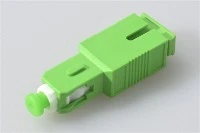
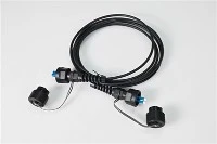
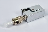
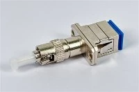
A single mode fiber patch cable is one of the most widely used fiber optic components in telecom networks, data centers, FTTH systems, enterprise backbones, and long-distance optical links. Built around a narrow 9/125µm glass core, it carries laser light in a single optical path, allowing signals to travel longer distances with lower attenuation and less distortion than multimode alternatives.
Whether you are specifying cables for a new data center build, upgrading an FTTH distribution cabinet, or replacing patch cords in a telecom central office, choosing the right single mode patch cable requires more than just picking a length and connector. You need to match the fiber type, connector interface, polish type, jacket rating, and optical performance to your transceiver, link budget, and installation environment.
This guide covers the fundamentals of single mode fiber patch cables - how they work, how they compare with multimode fiber, the key types available, where they are used, and a practical step-by-step process for selecting the right cable for your project.

What Is a Single Mode Fiber Patch Cable?
A single mode fiber patch cable - also called a single mode patch cord or single mode fiber jumper - is a pre-terminated fiber optic cable with connectors on one or both ends. It connects optical equipment such as switches, transceivers, patch panels, ODF frames, media converters, splitters, and terminal boxes.

Most single mode patch cables use 9/125µm fiber, where the first number refers to the core diameter (approximately 9 microns) and the second refers to the 125-micron cladding. According to the Fiber Optic Association (FOA), singlemode fiber at 9/125 microns is commonly associated with 1310nm and 1550nm wavelengths - the two primary operating windows for long-distance optical communication.
Unlike bulk fiber cable that is installed through conduits and terminated on site, a fiber optic patch cord arrives ready to plug in. This makes it the standard connection method inside equipment rooms, data center racks, FTTH distribution boxes, testing benches, and telecom cabinets.
Single mode patch cables are traditionally yellow-jacketed in indoor patching environments, but jacket color alone should never be the sole way to identify a cable. Always verify the printed jacket marking, fiber type designation, connector type, and polish specification before installation.
How Does a Single Mode Fiber Patch Cable Work?
A single mode fiber patch cable guides laser light through a very narrow glass core. Because the core diameter is small - roughly 8.6 to 9.5 microns according to ITU-T G.652 specifications - the light propagates in essentially one mode. This eliminates modal dispersion, which is the primary distance-limiting factor in multimode fiber, and allows cleaner signal transmission over tens or even hundreds of kilometers.
The fiber structure consists of two optical layers: the core, which is the central glass path where the light signal travels, and the cladding, a surrounding glass layer with a lower refractive index that confines light inside the core through total internal reflection.
Single mode fiber is optimized for operation at 1310nm and 1550nm. The 1310nm window offers near-zero chromatic dispersion for standard G.652 fiber, while the 1550nm window provides the lowest attenuation - typically around 0.2 dB/km for modern G.652.D fiber. These characteristics make single mode fiber the foundation of nearly all long-haul and metro optical networks.
In a real deployment, the patch cable does not work in isolation. Its performance depends on the optical transceiver, the total link loss budget, connector quality, and every splice and connection point in the path. A well-made patch cable with low insertion loss and high return loss contributes to link margin, but the complete system design determines whether the link performs reliably.
Single Mode vs Multimode Fiber Patch Cable: Key Differences
The fundamental difference between single mode and multimode fiber is core size and how light travels through it. Single mode fiber has a much smaller core and supports only one propagation mode, while multimode fiber uses a larger core that allows hundreds of modes to travel simultaneously - which causes modal dispersion and limits transmission distance.

| Feature | Single Mode Fiber Patch Cable | Multimode Fiber Patch Cable |
|---|---|---|
| Common fiber size | 9/125µm | 50/125µm (OM3/OM4/OM5) or 62.5/125µm (OM1/OM2) |
| Light source | Laser (DFB, FP) | LED or VCSEL |
| Typical wavelength | 1310nm / 1550nm | 850nm / 1300nm |
| Best suited for | Long-distance, high-capacity links | Short-distance links (typically under 300–550m) |
| Common applications | Telecom, FTTH, metro networks, data center interconnects | Data centers, LANs, short in-building links |
| Cable color | Usually yellow | Orange (OM1/OM2), aqua (OM3/OM4), or violet (OM5) |
| Transceiver cost | Often higher for long-reach modules | Often lower for short-reach VCSEL-based modules |
Single mode is the better fit when distance, scalability, and low attenuation are priorities. However, it is not always the most cost-effective choice for every link. For short-reach connections inside a data center - say, switch-to-server links under 100 meters - multimode fiber (OM3, OM4, or OM5) paired with VCSEL-based transceivers can be significantly cheaper. The right choice depends on the complete system: transceiver cost, link distance, existing cabling infrastructure, port density, and future upgrade path.
Common Types of Single Mode Fiber Patch Cables
Not all single mode patch cables are interchangeable. Before ordering, you need to confirm the fiber category, cable structure, connector type, polish type, jacket rating, and length.

Simplex vs Duplex Single Mode Patch Cables
A simplex patch cable contains one fiber strand and is used when only one optical path is needed - for example, in certain monitoring links, single-fiber bidirectional (BiDi) systems, or connections to individual splitter ports.
A duplex single mode patch cable contains two fibers in a zipcord structure, with one fiber for transmit and one for receive. This is the standard configuration for most Ethernet switch-to-switch, switch-to-transceiver, and patch panel connections. For high-density data center patching, LC duplex single mode patch cables are by far the most common choice.
OS2 Single Mode Fiber Patch Cable: When to Use It
OS1 and OS2 are both single mode fiber categories defined under ISO/IEC 11801, but they serve different roles. OS1 refers to tight-buffered indoor cable constructions with a maximum attenuation of 1.0 dB/km. OS2 refers to loose-tube or lower-attenuation constructions rated at 0.4 dB/km or better, suitable for both indoor and outdoor use.
Modern OS2 fiber is typically built on ITU-T G.652.D glass, which eliminates the water peak at 1383nm and supports full-spectrum operation from the O-band through the L-band (1260–1625nm). This makes OS2 compatible with CWDM systems and future wavelength upgrades.
For most new single mode patching projects - whether in a data center, telecom facility, or FTTH network - OS2 is the safer default. It gives better compatibility with modern long-distance transceivers and leaves more headroom for future bandwidth upgrades. OS1 may still appear in older indoor installations or very short backbone links, but there is little reason to specify it for new builds.
LC vs SC Single Mode Patch Cable: Which Connector Fits Your Equipment?

Connector choice is determined by the equipment interface, not by personal preference. Here are the most common connector types used with single mode patch cables:
| Connector | Common Use |
|---|---|
| LC | High-density data centers, SFP/SFP+/SFP28/QSFP modules, modern switches and routers |
| SC | FTTH ONTs, OLTs, telecom ODF panels, splitter ports, access network equipment |
| FC | Test and measurement equipment, laboratory setups, some industrial and military applications |
| ST | Legacy LAN installations and older network equipment |
In a high-density data center rack, LC patch cables are usually the first choice because their small form factor allows more ports per rack unit. In an FTTH distribution cabinet, SC connectors are often preferred because they are durable, easy to handle in the field, and widely used across PON equipment. FC and ST connectors appear less frequently in new enterprise installations, but they remain common in testing environments and certain industrial systems.
If the two devices you are connecting use different connector interfaces, choose a hybrid patch cable such as SC to LC or LC to FC.
UPC vs APC Fiber Connector: Choosing the Right Polish Type

The connector polish type directly affects return loss and determines whether a patch cable is suitable for reflection-sensitive systems.
| Polish Type | Connector Color | Typical Return Loss | Best For |
|---|---|---|---|
| UPC (Ultra Physical Contact) | Blue | ≥50 dB | Data centers, Ethernet, general digital transmission |
| APC (Angled Physical Contact) | Green | ≥60 dB | FTTH, PON, CATV, RF video, WDM systems |
UPC connectors use a flat, dome-shaped end face polished to a fine finish. APC connectors use an 8-degree angled end face that directs reflected light away from the fiber core, achieving significantly higher return loss. In PON and CATV systems, even small back-reflections can degrade signal quality or cause interference with analog video signals - which is why SC/APC connectors are standard in FTTH networks.
Warning: Do not connect an APC connector to a UPC connector. The angled and flat end-face geometries are physically incompatible. Mating them will cause an air gap that produces high insertion loss, poor return loss, and may permanently damage both ferrule surfaces. If you see a green connector on one end and a blue connector on the other, stop and verify before connecting.
Jacket Materials and Cable Ratings
The outer jacket determines where a patch cable can be safely installed and whether it meets local fire safety codes. Common options include:
PVC - general-purpose indoor jacket, adequate for most rack and equipment room environments. LSZH (Low Smoke Zero Halogen) - required in many public buildings, tunnels, transit systems, and enclosed spaces where toxic fumes from burning cable could endanger occupants. OFNR (Riser) - rated for vertical cable runs between floors. OFNP (Plenum) - rated for plenum air-handling spaces, which have the strictest fire code requirements in North American buildings. PE (Polyethylene) - outdoor-rated jacket for moisture and UV resistance. Armored - adds a metal or aramid layer for crush resistance, rodent protection, and mechanical durability in harsh environments.
For standard data center rack patching, 2.0mm or 3.0mm LSZH or PVC duplex cords are the norm. In high-density racks where hundreds of patch cables share limited tray space, a 2.0mm or 1.6mm cable can significantly improve airflow and cable management. For outdoor or industrial applications, armored fiber patch cables provide the necessary mechanical protection.
Where Are Single Mode Fiber Patch Cables Used?

Data Centers and High-Speed Interconnects
In data centers, single mode patch cables connect top-of-rack switches to spine switches, link patch panels in cross-connect areas, and terminate high-speed optical modules. For 100G links and beyond, single mode LC duplex OS2 cables paired with LR4 or ER4 transceivers are common for distances that exceed the reach of multimode VCSEL-based optics.
Telecom and 5G Transport Networks
Telecom operators depend on single mode fiber for fronthaul, midhaul, and backhaul connections. Patch cables are used extensively inside central offices, in optical distribution frames (ODFs), at cell tower base stations, and in metro ring interconnection points. Low attenuation and broad wavelength support make single mode the only practical choice for carrier-grade transport.
FTTH and FTTx Access Networks
Fiber-to-the-home networks typically use SC/APC single mode patch cords to connect OLTs, PLC splitters, distribution boxes, and ONTs. The APC polish is essential in PON architectures because the shared downstream signal is highly sensitive to back-reflection. In an FTTH cabinet, SC/APC is preferred because reflection control matters more than port density at the access layer.
Enterprise Campus and Building Backbones
For building-to-building links, campus backbone rings, and security or surveillance fiber runs, single mode patch cables provide far greater distance reach and bandwidth headroom than multimode. Even for links that are currently short, specifying single mode now avoids the cost of recabling when speeds upgrade from 10G to 25G, 100G, or beyond.
Industrial, Outdoor, and Harsh-Environment Networks
Mining operations, oil and gas facilities, transportation systems, highway monitoring networks, and outdoor surveillance deployments often use armored or ruggedized single mode patch cables to withstand vibration, moisture, temperature extremes, and physical stress.
How to Choose the Right Single Mode Fiber Patch Cable
Selecting the right patch cable is straightforward if you work through these steps systematically. The key is to match the cable specification to the equipment, environment, and link performance requirements - not to choose a cable in isolation.

Step 1: Confirm the Fiber Type and Link Requirements
Start with the fiber category. For nearly all new single mode projects, OS2 (based on G.652.D fiber) is the standard choice. Then check the transceiver datasheet for supported wavelength, maximum link distance, and transmit/receive power levels. The patch cable is one component in the total link - it must be compatible with the optical module and the overall loss budget.
Step 2: Match the Connector to Your Equipment Ports
Look at the physical port on your transceiver, patch panel, ODF, or terminal box. Common pairings include: SFP/SFP+/SFP28 modules typically require LC duplex connectors; FTTH ONT or splitter ports usually require SC/APC; ODF panels may use SC, LC, or FC depending on the design; test equipment often uses FC or SC with interchangeable adapters.
If the two endpoints use different connectors, order a hybrid patch cable - for example, SC/APC to LC/UPC for connecting an FTTH ODF to an Ethernet switch.
Step 3: Choose UPC or APC Polish
The simplest rule: if the equipment port is green or the system is PON, CATV, or RF-video related, use APC. For standard Ethernet and digital data transmission, use UPC. Always verify by checking the equipment manual or transceiver specification - some devices explicitly require one polish type, and using the wrong one will cause measurable performance degradation.
Step 4: Select the Jacket Rating and Cable Diameter
Choose the jacket material based on where the cable will be installed. For indoor data center cabinets, LSZH or PVC is common. For plenum airspaces in North American buildings, OFNP may be required by local code. For outdoor runs or physically demanding environments, select PE jacket or an armored construction.
Cable diameter is a practical choice: a 3.0mm cord is robust and easy to handle during installation, while a 2.0mm or 1.6mm cord is better for high-density patching where space and airflow matter.
Step 5: Verify Insertion Loss, Return Loss, and Test Documentation

A quality patch cable supplier should provide individual optical test results for each cable assembly. The key parameters to verify are:
Insertion loss (IL): For factory-terminated single mode patch cords, typical IL is ≤0.3 dB per connector, with many quality assemblies achieving ≤0.2 dB. The ANSI/TIA-568.3 standard sets a maximum connector loss of 0.75 dB for a mated pair, but this ceiling is deliberately generous to accommodate field-terminated and splice-on connectors. For factory-made patch cords, anything above 0.3 dB per mated connection warrants closer inspection.
Return loss (RL): UPC connectors should achieve ≥50 dB return loss; APC connectors should achieve ≥60 dB. These values are critical in reflection-sensitive systems and should be verified on the test report at both 1310nm and 1550nm.
End-face quality: Per IEC 61300-3-35, connector end faces should be inspected for scratches, defects, and contamination in the core and cladding zones before mating. A reliable supplier performs 100% end-face inspection and includes this data in the test report.
Step 6: Plan Length, Labeling, and Packaging
Choose a cable length that reaches comfortably without tension, but does not create excessive slack that leads to tangled cable trays and impaired airflow. Good cable management protects fiber from bend damage - remember that the minimum bend radius for standard single mode fiber is typically 30mm under load and 15mm when unloaded, though bend-insensitive G.657.A2 fiber can tolerate tighter radii down to 7.5mm.
For larger deployments, request clear per-cable labeling (with connector types, length, and loss data), packaging organized by link or rack, and test reports matched to individual assemblies. These details save significant time during installation and reduce field errors.
Selection Examples for Common Scenarios
To make the selection process more concrete, here are three typical scenarios:
Data center SFP+ 10G link (switch to patch panel, 15m): LC/UPC duplex, OS2 9/125µm, 2.0mm LSZH jacket, yellow. This is the standard configuration for most modern data center cross-connects.
FTTH terminal box connection (splitter to ONT, 3m): SC/APC simplex, OS2 9/125µm, 3.0mm PVC or LSZH jacket, yellow. The APC polish is required because PON systems are sensitive to back-reflection at every connection point.
Outdoor cabinet to base station (armored, 20m): SC/APC or LC/APC duplex, OS2 9/125µm, armored with PE outer jacket. The armored construction protects against rodent damage and mechanical stress in exposed environments.
Common Mistakes to Avoid
Mixing APC and UPC Connectors
This is one of the most frequent field errors. An APC ferrule polished at 8 degrees will not mate properly with a flat UPC ferrule. The result is an air gap that causes high insertion loss, elevated reflections, and potential physical damage to both end faces. Always match green to green and blue to blue.
Ignoring Transceiver Compatibility
A single mode patch cable must be paired with a single mode transceiver. Connecting a single mode cable to a multimode-only optical module - or vice versa - will result in excessive loss or no link at all. Always verify the transceiver specification before connecting.
Bending Fiber Beyond Its Minimum Radius
Every fiber cable has a minimum bend radius below which the light escapes the core, causing attenuation or permanent damage. Follow the manufacturer's bend radius specification and avoid sharp turns inside cable trays, patch panels, or rack enclosures. For standard G.652.D fiber, the minimum bend radius is typically 30mm. Bend-insensitive G.657.A1 or G.657.A2 fiber handles tighter bends, but should still be routed carefully.
Skipping End-Face Inspection and Cleaning
Dust and particulate contamination are the most common causes of unexpected insertion loss and link failures. Industry best practice - reinforced by IEC 61300-3-35 - is to inspect, clean, and re-inspect every connector end face before mating, using a fiber microscope and appropriate cleaning tools.
Choosing Cables Based Only on Price
A low-cost patch cable that arrives with inconsistent connector quality, missing test reports, or out-of-spec insertion loss will cost more in troubleshooting time and link instability than a properly qualified assembly. For professional networks, prioritize suppliers who provide per-cable test documentation, consistent connector quality, and responsive technical support.
What to Include When Requesting a Quote
When placing an order or sending an RFQ to a supplier, provide the following details to avoid specification gaps and production delays:
Fiber type: OS2 single mode (G.652.D), or specify if another type is required. Connector A: LC, SC, FC, ST, or other. Connector B: LC, SC, FC, ST, or other (specify if hybrid). Polish type: UPC or APC for each end. Cable structure: Simplex or duplex. Jacket material: PVC, LSZH, OFNR, OFNP, PE, or armored. Cable diameter: 0.9mm, 1.6mm, 2.0mm, 3.0mm, or custom. Length: Standard or custom, specify tolerance if critical. Quantity: Per length, per configuration. Optical performance requirements: Maximum insertion loss and minimum return loss per connector. Test report requirements: Per-cable IL and RL data at 1310nm and 1550nm, end-face inspection results. Labeling and packaging: Per-cable labels, rack-organized packaging, project-specific markings. Sample approval: Whether pre-production samples are required before bulk production.
For large-scale projects, requesting samples before bulk orders is a practical way to verify connector fit, cable flexibility, labeling quality, and test documentation before committing to full production volumes.
Frequently Asked Questions
What is a single mode fiber patch cable used for?
It connects optical equipment in networks that require long-distance, low-loss, and high-speed transmission. Typical applications include telecom transport networks, FTTH access networks, data center interconnects, enterprise campus backbones, ODF patching, and industrial fiber links.
Is single mode fiber always yellow?
Single mode patch cables are conventionally yellow, and this color coding is referenced in ANSI/TIA-568.3. However, color alone is not a reliable identifier. Always check the printed jacket marking and product specification to confirm fiber type.
What is the difference between OS1 and OS2 single mode fiber?
OS1 is a tight-buffered indoor cable category with a maximum attenuation of 1.0 dB/km. OS2 is a lower-attenuation category (≤0.4 dB/km) commonly built on G.652.D fiber, suitable for both indoor and outdoor applications. OS2 supports full-spectrum operation and is the standard choice for new single mode installations.
Can I use a single mode patch cable for short distances?
Yes. Single mode fiber works at any distance as long as the transceiver and receiver are compatible. For very short data center links, multimode fiber with VCSEL-based optics may be more cost-effective, but single mode is perfectly functional and offers more future-proof bandwidth headroom.
What is the difference between UPC and APC connectors?
UPC (Ultra Physical Contact) connectors have a flat polished end face and typically achieve ≥50 dB return loss. APC (Angled Physical Contact) connectors have an 8-degree angled end face that achieves ≥60 dB return loss by directing reflected light away from the core. APC is required for FTTH, PON, CATV, and other reflection-sensitive systems.
Can I connect an APC connector to a UPC connector?
No. The two end-face geometries are physically incompatible. Mating APC to UPC will cause high insertion loss, poor return loss, and may damage both connector ferrules. Always use matching polish types - APC to APC, or UPC to UPC.
Is LC or SC better for single mode patch cables?
Neither is universally better - the right choice depends on your equipment interface. LC is preferred in high-density data center environments because of its small form factor and compatibility with SFP-style transceivers. SC is standard in FTTH, telecom ODF, and access network applications because of its durability, ease of use, and wide adoption across PON equipment. See our guide on common fiber optic connectors for a more detailed comparison.
What does 9/125 mean in single mode fiber?
The numbers refer to the fiber's core and cladding diameters in microns. The core is approximately 9µm, and the cladding is 125µm. This is the standard geometry for all single mode fiber defined under ITU-T G.652.
Is single mode patch cable suitable for 10G, 40G, and 100G networks?
Yes. Single mode fiber supports all current Ethernet speeds from 1G through 400G and beyond, given the appropriate transceiver module. In fact, most 40G and 100G long-reach standards (such as 40GBASE-LR4 and 100GBASE-LR4 defined by IEEE 802.3) require single mode fiber.
How do I know if my existing fiber patch cable is single mode?
Check the printed text on the cable jacket. Single mode cables are usually marked with "9/125," "SM," or "OS2." A yellow jacket is a common visual indicator in indoor environments, but always verify with the jacket printing. If unsure, you can also test the cable with an optical power source at 1310nm or 1550nm - a multimode cable will show very high loss at these wavelengths if tested with a single mode source.
Can I use OS2 patch cable with OS1 infrastructure?
In most cases, yes. Both OS1 and OS2 use the same 9/125µm fiber geometry, so they are physically compatible and can be spliced or connected together. The main difference is in cable construction and attenuation rating. However, for loss budget calculations, use the attenuation specification of the weakest segment in the link.
Conclusion
A single mode fiber patch cable is a foundational component in optical networks - from telecom backbones to FTTH last-mile connections to high-speed data center fabrics. Choosing the right one requires attention to fiber type, connector interface, UPC or APC polish, jacket rating, and optical performance specifications.
Rather than selecting a cable based on length and price alone, match it to the full link design: the transceiver, the distance, the loss budget, the installation environment, and your test documentation requirements. For professional projects, the best single mode patch cable is the one that arrives with verified test data, installs cleanly, and performs reliably over its full service life.
If you need help specifying single mode patch cables for your project, or want to request samples before a bulk order, contact our engineering team for technical support and custom configuration options.