An Optical Distribution Frame (ODF) and a fiber optic patch panel both house adapters, organize cables, and mount inside 19-inch racks. From the outside, they look interchangeable. They're not. Each one handles a completely different stage of fiber connectivity, and installing the wrong device at the wrong point in your topology usually means ripping it out later.
| What is the difference between ODF and patch panel? Fiber Patch Panel vs ODF: Key Differences While fiber patch panels and ODFs are both integral components of fiber optic networks, there are some key differences: Purpose: Fiber patch panels are primarily used for connecting and managing fiber optic lines. Conversely, ODFs not only connect and manage but also protect the core, pigtail of the optical cable, and line adjustment. Design: Patch panels are usually simpler than ODFs, containing only patch panels and fiber optic adapters. ODFs, on the other hand, include patch panels, fiber optic adapters, and may also include other components like fiber optic transceivers, fiber optic switches, fiber optic attenuators, etc. Usage: ODFs are typically used in long-distance communication and large-scale networks, while patch panels are more commonly used in local networks and data centers. Scale: ODFs can usually accommodate more fiber connections, making them more suitable for large-scale network infrastructures. In summary, both fiber patch panels and ODFs serve to organize and manage fiber connections, but their design, usage, and application scenarios differ. When choosing between these devices, consider its purpose, network scale, and specific network requirements. |
What Exactly Is an Optical Distribution Frame (ODF)?
An ODF is where outside plant (OSP) fiber optic cables enter a facility and get organized for internal distribution. When a 288-fiber armored trunk cable arrives from the street, it doesn't plug directly into a switch. It enters the ODF, where technicians strip the outer jacket, separate individual fiber strands, and fusion-splice each one onto a fiber optic pigtail that provides a connectorized endpoint (typically SC, LC, or FC) for cross-connecting to internal distribution cables. In many FTTH deployments, the ODF also houses PLC splitter modules that divide a single feeder fiber into multiple subscriber branches before those branches leave the frame.
All of that splicing work needs a protected environment. ODF enclosures shield delicate fusion joints from dust, moisture, vibration, and accidental contact, while slide-out splice trays keep every splice point accessible for OTDR testing without disturbing adjacent fibers. Integrated cable management guides enforce minimum bend radius on each strand, which matters more than most people realize when hundreds of fibers share a single frame. A floor-standing ODF can accommodate 576, 864, or over 1,000 connections through modular tray configurations-the reason you'll find them in carrier central offices and campus entrance facilities where dozens of trunk cables converge.

What Is ODF and IDF?
ODF (Optical Distribution Frame) is a fiber optic management device used to terminate, connect, and protect fiber optic cables in telecom and data center environments. IDF (Intermediate Distribution Frame) is a secondary network distribution point that extends connectivity from the Main Distribution Frame (MDF) to individual floors or zones within a building. ODF manages fiber optic signals, while IDF distributes network connections to end users.
What Does a Fiber Optic Patch Panel Do?
A fiber optic patch panel is a rack-mounted enclosure that presents rows of adapters (LC duplex, SC simplex, MTP/MPO) on a front-facing plate. Behind the plate, pre-terminated trunk cables or pigtailed distribution fibers connect to the back of each adapter. A technician with a 3-meter fiber optic patch cord plugs into the front side and completes the circuit to active equipment-a switch, a server, a media converter.
No fusion splicer, no splice trays. Plug in a patch cord to bring a new server online, unplug it to decommission. Moves, adds, and changes (MACs) happen in seconds. Modern high-density panels pack 24 LC duplex ports (48 fibers) into a single rack unit, with MTP cassette designs pushing that to 96 or 144 fibers per unit. In data centers where every rack unit represents real estate cost, that density drives most purchasing decisions.
Key Differences Between ODF and Patch Panel
An ODF is where raw outside plant cables get permanently terminated through fusion splicing-joints that may go untouched for a decade. A patch panel is entirely connector-based: every connection is designed to be made and broken by hand, as often as the network demands. The differences between fiber pigtails and patch cords mirror this same permanent-versus-flexible divide at the component level.
Location, construction, and capacity all follow from that one fact. ODFs sit at cable entrance facilities, main distribution frames, and meet-me rooms-built with heavy-gauge steel enclosures, integrated strain relief, and generous routing space because they're handling armored outdoor trunks. Patch panels live inside equipment racks next to switches and routers, lighter and slide-rail-mounted, because their job is clean patch cord management in a controlled indoor environment. And while an ODF installation might manage thousands of fiber strands across multiple frames, a patch panel optimizes for port-per-rack-unit density-fewer total fibers, packed tightly enough to serve a full equipment cabinet without wasting vertical space.
Where Each One Fits in a Real Deployment

In a typical FTTH or FTTP network, a carrier-grade ODF sits at the central office or field cabinet. It receives feeder cables from the backbone, splices them into distribution fibers, and often houses PLC fiber optic splitters that divide one upstream fiber into 16 or 32 subscriber branches. From there, distribution cables fan out to street-level terminals and subscriber premises.
Data centers work the other way around. Trunk fibers from the campus backbone terminate at an ODF in the main fiber entrance room, but the day-to-day action happens at the row level, where high-density patch panels give administrators the port connections they plug and unplug as workloads shift. A branch office or single-floor fit-out simplifies things further: if the service provider delivers pre-terminated fiber, a compact wall-mount patch panel handles the entire site without any splicing at all.
Most well-designed networks use both in tandem. The ODF handles trunk cable termination and long-term cross-connects; the patch panel provides flexible last-meter connectivity to equipment ports. This layered approach isolates the sensitive splice environment from everyday patching, reducing the risk of accidental fiber damage. It also means that when a network expansion arrives-a new switch, a new row of servers-the only hardware that needs to change is at the patch panel level, not inside the ODF.
Why Connector Quality Shapes the Whole System
The ODF and patch panel get most of the attention in planning discussions, but the connectors are doing the actual optical work. Adapter ports, pigtail terminations, patch cord mating surfaces-they all add insertion loss, and that loss accumulates. In a 144-fiber ODF serving a dense FTTH split, a 0.1 dB difference per connector stacks up quickly across hundreds of mated pairs.
Most of the performance gap between a good connector and a bad one lives in the ferrule. Precision-polished zirconia ceramic keeps fiber cores aligned within sub-micron tolerances; poorly finished end faces generate return loss spikes that degrade high-speed signals-particularly on 100G-and-above coherent links where every tenth of a dB counts. Inside an ODF, connector quality matters even more than at the patch panel, because a pigtail that's been fusion-spliced and seated in its adapter is meant to stay for the life of the cable plant. A bad fiber optic connector buried inside a splice tray isn't something you swap out on a Tuesday afternoon.
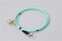
Form factor plays into density as well. LC connectors with their 1.25 mm ferrule deliver roughly double the port count per rack unit compared to SC's 2.5 mm form factor, which is why LC dominates modern data center patch panels and is increasingly showing up in ODF adapter sections. SC and FC still hold ground in legacy telecom plants where backward compatibility outweighs density gains.
Matching the Right Equipment to Your Network Scale
A 12-fiber branch office link and a 1,500-fiber carrier headend have almost nothing in common from a hardware perspective, and over-specifying wastes money just as reliably as under-specifying causes outages.
At the lighter end-fewer than 48 fibers-a wall-mount or 1U rack-mount patch panel handles the job on its own. A SOHO office connecting to a GPON ONT, for instance, might only need a 4- or 8-port fiber termination panel near the building entry point. The cables arrive pre-terminated, so there's nothing to splice and no reason to invest in ODF-level infrastructure.
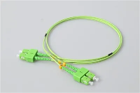
Once the fiber count crosses into the 48-to-288 range, a single patch panel won't cut it. A multi-floor enterprise campus or regional ISP node at this scale benefits from pairing a dedicated ODF at the main entrance facility with rack-mount patch panels in each IDF closet. The ODF provides a clean cross-connect layer for trunk splices, while the downstream panels let local IT staff reroute connections without ever opening a splice tray. Selecting the right fiber optic connector types at each tier-APC polish for long-haul splitter feeds, UPC for short-reach data links-prevents reflectance issues from cascading between layers. This is also the scale where labeling and documentation start to pay off; without a clear port map linking ODF splice positions to downstream patch panel ports, troubleshooting a single failed link can eat an entire afternoon.
Beyond a few hundred fibers, the ODF becomes permanent building infrastructure. Hyperscale data centers and telecom central offices at this scale need modular floor-standing systems with stackable splice trays, integrated routing channels, and front-access adapter panels that allow hot-aisle maintenance without disrupting adjacent connections. Hardware installed here is expected to last 15 to 20 years. High-grade singlemode pigtails and factory-tested adapters at the ODF level cost more upfront, but they eliminate the steady stream of field troubleshooting calls that cheap components generate over time.
Cable Management: The Overlooked Factor That Extends Hardware Life
How fiber gets routed through an ODF or patch panel affects performance just as much as the hardware itself. Bend radius violations, tangled patch cords, and cramped slack storage all introduce loss that shows up in OTDR traces but rarely gets blamed on the right cause.
Singlemode fiber (standard G.652) has a minimum bend radius around 15 mm, and violating it introduces macrobend loss that silently drains your link budget. Inside an ODF, the highest-risk zones are the pigtail exit points where fibers loop from splice trays to adapter panels and the slack storage areas where excess fiber gets coiled. Curved routing channels and mandrel-style spool holders in a well-engineered ODF keep every strand above minimum radius-even when a technician slides the tray out for maintenance and pushes it back in.
At the patch panel, the problem shifts from internal bends to external cord management. A 48-port LC panel in a busy data center accumulates dozens of cords cascading from its front face, and without horizontal and vertical cable managers, those cords tangle, drag on connector bodies, and load the ferrule spring with constant lateral force. That mechanical pressure accelerates end-face wear and gradually increases insertion loss-a problem that Velcro ties, proper service loops, and consistent labeling can prevent entirely if the discipline is there from day one.
ODF layout also affects how often connectors get disturbed downstream. When trunk fibers have adequate service slack and clean routing paths, OTDR tests and maintenance splices happen without pulling or torquing any fiber. Every time a connector gets stressed, unplugged, and re-seated, its end face picks up contamination and micro-scratches. Designing for low-force access from the start means fewer maintenance touches-and fewer maintenance touches means longer connector life.
Putting It All Together
ODF or patch panel is not an either/or decision for most networks-it's a question of which device goes where. The ODF terminates trunk cables and provides long-term cross-connects. The patch panel gives technicians a flexible patching layer close to the equipment. Getting that topology right is step one.
Step two is everything around it: ferrule quality and polish grade matched to each layer, enclosure sizing based on actual fiber counts instead of guesswork, and cable routing that protects connectors from unnecessary mechanical stress. None of that is glamorous work, but it's the difference between a fiber plant that runs cleanly for 15 years and one that generates a service call every quarter.