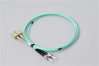
A deep-dive technical comparison to help network engineers and procurement teams select the right multimode fiber for their infrastructure
When a logistics company in New Jersey reached out to us last quarter about upgrading their warehouse network, they faced a common dilemma: their existing OM1 cabling couldn't support the 10GbE switches they'd just purchased. The technician on-site had recommended OM4, but was that overkill for runs averaging 85 meters? This scenario plays out daily across data centers, campuses, and enterprise facilities worldwide.
Multimode fiber selection isn't just about picking a color-coded cable-it's about understanding the physics of light propagation, matching your infrastructure to current and future bandwidth demands, and optimizing your capital investment. This guide goes beyond surface-level specifications to explain why these fibers perform differently and how to make informed decisions for your specific deployment.
What Makes Multimode Fiber "Multimode"
Before diving into the OM classifications, let's establish what distinguishes multimode fiber from its single-mode counterpart at a fundamental level.
Multimode fiber features a larger core diameter-typically 50μm or 62.5μm compared to single-mode's 9μm core. This larger core allows light to travel through the fiber along multiple paths simultaneously, each path representing a different "mode" of propagation. Think of it like a highway with many lanes versus a single-lane road: more lanes mean more traffic capacity over short distances, but coordination becomes challenging over longer stretches.
The core-to-cladding interface in graded-index multimode fiber isn't a sharp boundary but rather a gradual transition in refractive index. This gradient is precisely engineered to equalize the travel time of different modes. Light traveling near the fiber's edge takes a longer physical path but moves through lower-refractive-index material (and thus travels faster), while light near the center takes a shorter path through higher-refractive-index material (moving slower). When perfectly tuned, all modes arrive at the receiver simultaneously.
In practice, manufacturing tolerances mean this compensation is never perfect. The resulting timing differences between modes-called modal dispersion-ultimately limit the fiber's bandwidth and transmission distance. This is the key parameter that separates OM1 through OM5.
The Evolution from LED to VCSEL: Understanding the Bandwidth Revolution
The OM classification system reflects a fundamental shift in light source technology that occurred in the late 1990s and early 2000s.
The LED Era (OM1 and OM2)
Early multimode systems used Light-Emitting Diodes (LEDs) as their light source. LEDs produce a broad, uniform output that fills the entire fiber core, exciting all available modes simultaneously. This "overfilled launch" condition meant the fiber's bandwidth was determined by the aggregate performance of hundreds of modes working together. A few slow or fast modes had minimal impact because the signal energy was distributed across so many paths.
LEDs have a fundamental limitation: their maximum modulation rate tops out around 622 Mbit/s. This constraint made them unsuitable for gigabit-speed applications, regardless of the fiber's theoretical capability.
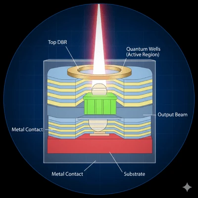
The VCSEL Revolution (OM3, OM4, OM5)
Vertical-Cavity Surface-Emitting Lasers (VCSELs) changed everything. These semiconductor lasers offer:
Modulation rates exceeding 25 Gbit/s (and continuing to improve)
Narrower spectral width, reducing chromatic dispersion
Higher optical power for improved signal-to-noise ratios
Lower manufacturing costs compared to edge-emitting lasers
Circular beam profiles that couple efficiently into fiber cores
However, VCSELs don't fill the fiber core uniformly. Their concentrated beam excites only a subset of available modes-typically those near the fiber's center. This "restricted launch" condition means any defects or refractive index variations in the core center disproportionately impact system performance.
This is why OM1 and OM2 fibers, designed for overfilled LED launches, often perform worse with VCSELs than their rated bandwidth would suggest. Fiber manufacturers responded by developing laser-optimized multimode fiber (LOMMF) with tightly controlled refractive index profiles specifically designed for VCSEL launches. This laser-optimized fiber became the foundation for OM3, OM4, and OM5 classifications.
OM Classifications: Detailed Technical Breakdown
OM1 Fiber
Core Specifications:
Core diameter: 62.5μm
Cladding diameter: 125μm
Overfilled Launch (OFL) bandwidth: 200 MHz·km at 850nm, 500 MHz·km at 1300nm
Maximum attenuation: 3.5 dB/km at 850nm, 1.5 dB/km at 1300nm
Jacket color: Orange (per TIA-598C)
Technical Context:
OM1's larger 62.5μm core was originally chosen because it simplified alignment with LED sources and allowed for looser connector tolerances. However, this larger core supports more propagation modes than 50μm fiber, resulting in greater modal dispersion and lower bandwidth.
The 62.5μm core size creates a fundamental incompatibility: OM1 connectors and patch cords cannot be mixed with OM2/OM3/OM4/OM5 components. Mating a 62.5μm fiber to a 50μm fiber results in approximately 3-4 dB of additional loss-enough to cause link failures in many systems.
Practical Distance Limits:
| Data Rate | Maximum Distance |
|---|---|
| 100 Mbit/s (100BASE-FX) | 2,000 m |
| 1 Gbit/s (1000BASE-SX) | 275 m |
| 10 Gbit/s (10GBASE-SR) | 33 m |
Current Status:
OM1 is considered legacy infrastructure. New installations should not specify OM1 unless connecting to existing 62.5μm plant where modal continuity is required. The 33-meter limit at 10GbE makes it impractical for modern data center applications.
OM2 Fiber
Core Specifications:
Core diameter: 50μm
Cladding diameter: 125μm
OFL bandwidth: 500 MHz·km at 850nm, 500 MHz·km at 1300nm
Maximum attenuation: 3.5 dB/km at 850nm, 1.5 dB/km at 1300nm
Jacket color: Orange (per TIA-598C)
Technical Context:
OM2 represents the transition to 50μm core technology while still being designed primarily for LED sources. The smaller core reduces the number of supported modes, improving bandwidth compared to OM1. Modern OM2 is often manufactured as laser-optimized, though it doesn't meet the stringent EMB requirements of OM3.
Because both OM1 and OM2 use orange jackets, always verify the fiber type by checking the cable's printed legend (e.g., "50/125" vs "62.5/125") before termination or splicing.
Practical Distance Limits:
| Data Rate | Maximum Distance |
|---|---|
| 100 Mbit/s (100BASE-FX) | 2,000 m |
| 1 Gbit/s (1000BASE-SX) | 550 m |
| 10 Gbit/s (10GBASE-SR) | 82 m |
Current Status:
Like OM1, OM2 is being phased out of new installations. The 82-meter limit at 10GbE constrains its usefulness in modern environments, though it remains serviceable for 1GbE connections within its distance limits.
OM3 Fiber (Laser-Optimized Multimode Fiber)

Core Specifications:
Core diameter: 50μm
Cladding diameter: 125μm
Effective Modal Bandwidth (EMB): 2,000 MHz·km at 850nm
OFL bandwidth: 1,500 MHz·km at 850nm
Maximum attenuation: 3.0 dB/km at 850nm
Jacket color: Aqua (per TIA-598C)
Technical Context:
OM3 was the first fiber classification designed specifically for VCSEL transmission. The key metric shifted from Overfilled Launch bandwidth (relevant for LEDs) to Effective Modal Bandwidth (relevant for VCSELs). EMB is determined through Differential Mode Delay (DMD) testing, which measures how different mode groups are delayed relative to each other under restricted launch conditions that simulate VCSEL behavior.
The 2,000 MHz·km EMB specification means a 300-meter link provides approximately 6.67 GHz of usable bandwidth-sufficient for 10GbE with margin. The fiber's refractive index profile is tightly controlled, particularly in the core center where VCSEL energy concentrates.
Practical Distance Limits:
| Data Rate | Maximum Distance |
|---|---|
| 1 Gbit/s (1000BASE-SX) | 550+ m |
| 10 Gbit/s (10GBASE-SR) | 300 m |
| 25 Gbit/s (25GBASE-SR) | 70 m |
| 40 Gbit/s (40GBASE-SR4) | 100 m |
| 100 Gbit/s (100GBASE-SR4) | 70 m |
Current Status:
OM3 remains widely deployed and cost-effective for 10GbE applications within 300 meters. For residential fiber installations and smaller enterprise networks where cable runs stay under 300 meters, OM3 offers excellent value. However, 40GbE and 100GbE applications quickly expose its limitations.
OM4 Fiber

Core Specifications:
Core diameter: 50μm
Cladding diameter: 125μm
Effective Modal Bandwidth (EMB): 4,700 MHz·km at 850nm
OFL bandwidth: 3,500 MHz·km at 850nm
Maximum attenuation: 3.0 dB/km at 850nm
Jacket color: Aqua or Erika Violet (per TIA-598C)
Technical Context:
OM4 emerged from continued refinement of the manufacturing process after OM3's introduction. Fiber producers achieved tighter control over the refractive index profile, more than doubling the effective modal bandwidth. This wasn't a new fiber design so much as an evolution of OM3 manufacturing to higher quality standards.
The 4,700 MHz·km EMB allows a 400-meter link to support approximately 11.75 GHz of bandwidth, enabling 10GbE over distances that would exceed OM3's capability. More importantly, OM4 extends the reach of 40GbE and 100GbE systems from OM3's 100m/70m limits to 150m/100m respectively.
OM4 is fully backward compatible with OM3-both use 50μm cores and can be interconnected without modal mismatch losses. The primary visual distinction is the optional Erika Violet (magenta) jacket color, though many manufacturers still use aqua.
Practical Distance Limits:
| Data Rate | Maximum Distance |
|---|---|
| 1 Gbit/s (1000BASE-SX) | 550+ m |
| 10 Gbit/s (10GBASE-SR) | 400 m (extended reach: 550 m) |
| 25 Gbit/s (25GBASE-SR) | 100 m |
| 40 Gbit/s (40GBASE-SR4) | 150 m |
| 100 Gbit/s (100GBASE-SR4) | 100 m (OM4 extended: 150 m) |
Current Status:
OM4 is the recommended choice for new data center installations supporting 10GbE through 100GbE. Its price premium over OM3 is modest (typically 10-20%), while its extended reach provides meaningful operational flexibility and future-proofing.
OM5 Fiber (Wideband Multimode Fiber)
Core Specifications:
Core diameter: 50μm
Cladding diameter: 125μm
EMB at 850nm: 4,700 MHz·km (same as OM4)
EMB at 953nm: 2,470 MHz·km (new specification)
Maximum attenuation: 3.0 dB/km at 850nm, 2.3 dB/km at 953nm
Jacket color: Lime Green (per TIA-598C)
Technical Context:
OM5 represents a paradigm shift in multimode fiber design. While OM3 and OM4 optimized bandwidth at the traditional 850nm VCSEL wavelength, OM5 extends this optimization across a wavelength range from 850nm to 953nm.
This wideband capability enables Short Wavelength Division Multiplexing (SWDM), where four wavelengths (850nm, 880nm, 910nm, and 940nm) transmit simultaneously over a single fiber pair. SWDM effectively quadruples the fiber's capacity without requiring additional fiber strands or transitioning to parallel optics.
Critical Clarification: OM5's EMB at 850nm equals OM4's specification. For single-wavelength 850nm transceivers (standard 10GbE, 25GbE, 40GbE SR4, 100GbE SR4), OM5 provides no distance advantage over OM4. The OM5 premium only pays dividends when using SWDM-capable transceivers like 40G-SWDM4, 100G-SWDM4, or emerging 400G-BD4.2 modules.
Practical Distance Limits:
| Data Rate | Standard Transceivers | SWDM Transceivers |
|---|---|---|
| 10 Gbit/s | 400 m (same as OM4) | N/A |
| 40 Gbit/s | 150 m (same as OM4) | 440 m (40G-SWDM4) |
| 100 Gbit/s | 100 m (same as OM4) | 150 m (100G-SWDM4) |
| 400 Gbit/s | N/A | 100 m (400G-BD4.2) |
Current Status:
OM5 adoption has been slower than initially anticipated. The cost premium (typically 30-50% over OM4) is difficult to justify unless SWDM transceivers are part of the deployment plan. For most data center applications, OM4 combined with parallel optics (MPO/MTP connectivity) achieves similar or better cost-effectiveness for 40GbE and 100GbE.
OM5 shows promise for hyperscale environments where fiber strand count is constrained or where the migration path to 400GbE and beyond favors wavelength multiplexing over fiber parallelism.
Comprehensive Comparison Table
| Specification | OM1 | OM2 | OM3 | OM4 | OM5 |
|---|---|---|---|---|---|
| Core Diameter | 62.5μm | 50μm | 50μm | 50μm | 50μm |
| Cladding Diameter | 125μm | 125μm | 125μm | 125μm | 125μm |
| Jacket Color | Orange | Orange | Aqua | Aqua/Violet | Lime Green |
| Light Source | LED | LED/VCSEL | VCSEL | VCSEL | VCSEL |
| OFL Bandwidth (850nm) | 200 MHz·km | 500 MHz·km | 1,500 MHz·km | 3,500 MHz·km | 3,500 MHz·km |
| EMB (850nm) | N/A | N/A | 2,000 MHz·km | 4,700 MHz·km | 4,700 MHz·km |
| EMB (953nm) | N/A | N/A | N/A | N/A | 2,470 MHz·km |
| Max Attenuation (850nm) | 3.5 dB/km | 3.5 dB/km | 3.0 dB/km | 3.0 dB/km | 3.0 dB/km |
| 10GbE Max Distance | 33 m | 82 m | 300 m | 400 m | 400 m |
| 40GbE SR4 Max Distance | N/A | N/A | 100 m | 150 m | 150 m |
| 100GbE SR4 Max Distance | N/A | N/A | 70 m | 100 m | 100 m |
| SWDM Support | No | No | No | No | Yes |
| Standard | ISO/IEC 11801, TIA-568 | ISO/IEC 11801, TIA-568 | ISO/IEC 11801, TIA-568 | TIA-492AAAD (2009) | TIA-492AAAE (2016) |
Selecting the Right Fiber: Decision Framework
Assessment Criteria
1. Current Bandwidth Requirements
Map your existing network topology and identify the speed of each link. If you're running primarily 1GbE connections, even OM3 provides substantial headroom. However, if 10GbE or faster links are prevalent, OM4 becomes the practical minimum for most environments.
2. Cable Run Distances
Measure or estimate your longest potential cable runs. Include slack loops, vertical risers, and routing detours-installed cable length often exceeds straight-line distance by 20-40%.
| If Longest Run Is... | Minimum Recommendation |
|---|---|
| Under 100 m | OM3 (adequate for 100GbE) |
| 100-150 m | OM4 (required for 40G/100G) |
| 150-300 m | OM4 (10GbE only at this range) |
| 300-400 m | OM4 (10GbE extended reach) |
| Over 400 m | Consider single-mode OS2 |
3. Future Migration Path
Data center bandwidth demands typically grow 25-50% annually. A cabling infrastructure installed today should accommodate at least 2-3 technology generations. For most organizations, this means designing for 40GbE/100GbE even if current equipment operates at 10GbE.
4. Budget Constraints
While OM4 carries a modest premium over OM3, the labor cost of cable installation typically dwarfs the material cost difference. Installing OM4 today versus OM3 may add 10-20% to cable procurement but avoids the far greater expense of re-cabling later.
Recommendation Summary
| Application Scenario | Recommended Fiber |
|---|---|
| Legacy system maintenance | Match existing infrastructure (OM1/OM2) |
| Small office/campus 1GbE | OM3 |
| Enterprise 10GbE backbone | OM4 |
| Data center (10G/25G/40G/100G) | OM4 |
| Hyperscale with SWDM roadmap | OM5 |
| Runs exceeding 400m | Single-mode OS2 |
Connector Selection and Best Practices
Multimode fiber performance depends critically on connector quality and cleanliness. For high-density data center applications, our MPO/MTP solutions support 8, 12, 16, and 24-fiber configurations for parallel optics transceivers. For traditional duplex connections, LC connectors offer the highest port density with our precision ceramic ferrules ensuring consistent sub-0.2dB insertion loss.
Polish Types
PC (Physical Contact): Basic polish, adequate for most multimode applications. Return loss typically >30dB.
UPC (Ultra Physical Contact): Enhanced polish with better surface finish. Return loss typically >50dB. Recommended for high-speed applications.
APC (Angled Physical Contact): 8-degree angled polish minimizes back-reflection. Return loss >60dB. Primarily used with single-mode fiber but available for specialized multimode applications.
Cleaning Protocol
Contamination is the leading cause of link failures. Even a single 1μm dust particle can block significant light transmission through a 50μm core. Before every mating, inspect connector end-faces with a 200x or higher magnification fiber scope and clean with lint-free wipes using IPA (isopropyl alcohol) or dry cleaning cassettes.
Making the Business Case: Total Cost of Ownership
The cost difference between multimode fiber grades is often less significant than it appears:
Material Cost Example (100m patch cord):
OM3: ~$45
OM4: ~$52 (15% premium)
OM5: ~$68 (51% premium over OM3)
Installation Labor (same for all grades): ~$150-300 per run
When installation labor dominates total cost, the incremental expense of specifying OM4 over OM3 becomes negligible-while the insurance against future bandwidth constraints is substantial.
For new data center construction, we recommend OM4 as the default specification. The modest upfront investment ensures compatibility with 10GbE, 25GbE, 40GbE, and 100GbE equipment without distance limitations within typical rack-to-rack and row-to-row distances.
Evolux Fiber Solutions for Your Multimode Infrastructure
At Evolux Fiber, we manufacture the complete ecosystem of multimode fiber connectivity components:
Fiber Optic Patch Cords: Pre-terminated OM3, OM4, and OM5 assemblies in simplex, duplex, and MPO/MTP configurations. Custom lengths from 0.3m to 100m+ with rapid turnaround.
Fiber Optic Connectors: LC, SC, FC, ST, and MPO/MTP connectors with precision zirconia ceramic ferrules. Insertion loss <0.2dB, return loss >50dB. Available in PC, UPC, and APC polish types.
Fiber Optic Pigtails: Factory-polished pigtails for fusion splicing applications. OS2 single-mode and OM1-OM5 multimode variants with LSZH or PVC jackets.
Fiber Optic Adapters: Panel-mount and bulkhead adapters with bronze or ceramic alignment sleeves. Simplex, duplex, and quad configurations.
PLC Splitters: 1x2 through 1x64 split ratios in bare fiber, ABS module, LGX cassette, and rack-mount packages for FTTH/PON deployments.
Terminal Boxes and Distribution Frames: Wall-mount and rack-mount enclosures with integrated splice trays and patch panels for organized cable management.
Our manufacturing facility in Shenzhen maintains ISO 9001 certification with rigorous quality control including 100% optical testing of every terminated assembly. With 12+ years of industry experience and an annual capacity exceeding 50 million connectivity components, we serve telecom operators, data center builders, and enterprise customers across 50+ countries.
Whether you need standard catalog products with next-day shipping or custom-engineered solutions for specific deployment requirements, our technical team is ready to support your project from design through installation.

Need help selecting the right multimode fiber solution?
Contact our engineering team for a complimentary consultation and project-specific recommendations.
Related Reading:
Single Mode vs Multimode Fiber: 2026 Complete Guide
MPO/MTP Fiber: The Real Talk You Need Before Your Next Data Center Build
All-Optical Campus Connector Selection: A Practical POL Cabling Guide