Evolux Fiber Team · Feb 2026 · 10 min read
Fiber optic installation is a critical step in building high-performance networks. Selecting the right cable ensures efficient data transmission, longevity, and durability across different environments. This guide covers indoor fiber optic cable and outdoor fiber optic cable installation, with practical tips for each scenario.
New to fiber optics? You might want to check our fiber optic connector basics first.
Types of Fiber Optic Cable by Application
Fiber optic cables are categorized based on their deployment environment: indoor and outdoor. Each type is designed with specific features to handle different conditions.
Indoor Fiber Optic Cables
Indoor fiber optic cables are commonly used in buildings, offices, and data centers. These cables are flexible, lightweight, and designed with fire-resistant materials to meet safety codes. They experience less environmental stress than outdoor cables but must comply with stringent fire safety standards.
Fire rating matters more than most people realize. In a building fire, the wrong cable jacket can release toxic fumes or spread flames through air handling spaces. Per NEC (National Electrical Code) Article 770, here's what you need to know about ratings:
|
Rating |
Full Name |
Where Required |
What Happens in Fire |
|
OFNP |
Optical Fiber Nonconductive Plenum |
Air handling spaces, drop ceilings with HVAC |
Won't produce toxic smoke, won't spread flames |
|
OFNR |
Optical Fiber Nonconductive Riser |
Vertical runs between floors |
Won't spread fire vertically |
|
LSZH |
Low Smoke Zero Halogen |
Transit systems, confined spaces |
Minimal smoke, no toxic halogen gases |
Using the wrong rating isn't just a code violation. We've seen installers run OFNR cable through plenum spaces to save a few cents per foot. Building inspector catches it, everything gets ripped out and redone with proper cable. The "savings" cost about 10x more in the end.
Outdoor Fiber Optic Cables
Outdoor cables face a completely different set of challenges-temperature swings from -40°C to +70°C, moisture infiltration, UV degradation, physical stress, and sometimes rodents chewing through the jacket. These cables are built tougher with armored jackets and water-blocking materials.
Underground Fiber Cables
These cables are pulled through conduits buried 1 to 2 meters deep. The conduit provides physical protection, but moisture still gets in over time-that's why underground cables need water-blocking gel or dry-block tape inside. Lubricant-compatible jackets help reduce friction during long pulls through the conduit system.
Direct Buried Cables
Unlike underground cables, direct buried cables go into the ground without conduits. They need reinforced armor-corrugated steel or aluminum tape-to handle soil pressure and rodent damage. Evolux offers armored cables with enhanced protection specifically designed for direct burial applications.
Aerial Cables
Aerial cables hang between poles or attach to buildings. They're protected from underground hazards but face wind loading, ice accumulation, and constant UV exposure instead. Self-supporting designs with built-in steel messenger wire are standard-the messenger bears the cable weight while the optical fibers stay protected inside.
Submarine Cables
For underwater deployment in rivers, lakes, or coastal areas, cables need superior water resistance. Most use multiple barriers: gel-filled tubes, water-swellable tapes, and hermetically sealed construction. Heavy armor protects against anchor strikes.
Pre-Installation Planning
Here's something most guides don't emphasize enough: planning prevents about 95% of installation problems. Not technique issues-planning issues. Someone forgot to check if the existing conduit was already full. Someone didn't realize a permit was needed for the road crossing. Someone ordered cable 20 meters short.
Before ordering anything, walk the entire route and document:
Total distance - measure it, don't estimate. Add 10-15% for slack and routing variations.
Obstacles - walls, ceilings, existing utilities, road crossings
Environmental conditions - will it be exposed to temperature extremes? Moisture? Chemicals?
Existing infrastructure - can you use existing conduits, cable trays, or pathways?
Permits required - excavation permits, building permits, right-of-way agreements
For outdoor work, call 811 (in the US) to locate existing underground utilities before any digging. This is legally required, and hitting a gas line or power cable creates serious problems.
Best Practices for Fiber Optic Installation
Fiber cables offer great advantages-high bandwidth, low loss, immunity to electromagnetic interference. But these benefits only show up when installation is done right. Here's targeted advice for different installation scenarios.
Indoor Fiber Optic Installation
Ceiling & Raised Floor Installations
Drop ceilings and raised floors are probably the easiest places to run fiber. The ceiling panels can usually be pushed up and moved aside, giving you access to route cables above. Raised floor tiles lift out the same way.

Cables in these spaces should be well-supported and organized. Use trays, J-hooks, or velcro straps-spacing about 4 to 5 feet apart on straight runs, with extra supports at direction changes.
One thing people forget: attach supports to the building structure, not the ceiling grid. The grid is only designed to hold tile weight. We've seen ceiling sections come down when too many cables got attached to the grid over time. It doesn't happen immediately-takes months or years of accumulated weight-but when it goes, it takes out everything underneath.
A few other things to watch for in ceiling installations:
Don't lay cables directly on ceiling tiles. They'll sag and eventually fall.
Don't cinch zip ties too tight. Creates stress points that cause problems later. Velcro straps work better.
Keep fiber separated from power cables by at least 12 inches. Fiber is immune to interference, but power cables generate heat.
In-Cabinet Installations
Cables inside rack cabinets need to be organized. Messy racks cause real problems-harder to troubleshoot, easier to accidentally disconnect something, nightmare to make changes later.

Use fiber patch panels for clean termination points. Route cables through vertical and horizontal cable managers rather than letting them drape across equipment. Keep fiber and power cables on opposite sides of the rack.
Always leave service loops-extra cable coiled up for future use. Without slack, even moving equipment a few inches might require pulling new cables.
Riser Installations
Vertical cable runs between floors are tricky because of cable weight. The cable itself can stretch over time if not properly supported.
Use OFNR-rated cable minimum for risers-OFNP if the riser connects to plenum spaces. Support cables at regular intervals using fiber-rated clamps. Regular metal clamps can crush the fiber if overtightened.
Here's a tip that saves a lot of effort: start from the top floor and pull down, not up. Pulling cable upward fights gravity the whole way, and the load increases with every meter you pull. Pulling down lets gravity help instead of fight you.
Maybe the handling procedures from different cable manufacturers vary a bit. So check the cable datasheet for maximum vertical rise without support, and follow their instructions first.
Outdoor Fiber Optic Installation
Conduit Installation
Conduit gives good long-term protection for outdoor cables, but once it's installed, making changes is difficult and expensive. Plan the route carefully upfront.

When pulling cable through conduit, keep all transition points smooth. At junction boxes and handholes, don't let cables rest on sharp edges-add a short piece of flexible conduit or innerduct to guide the cable around corners. Pull boxes break up long runs into manageable segments and give you access for future work.
Always put a pull rope in the conduit during installation. You'll need it later. Use fiber-compatible lubricant for long pulls-water-based gel works well, but verify it's compatible with your cable jacket material.
Note: The inside radius of conduit bends should be at least 10 times the cable outer diameter. For a typical 8mm outdoor cable, that's minimum 80mm bend radius. Conduit runs should be limited to 100 feet between pull points, with no more than two 90-degree bends per segment. Exceeding these limits dramatically increases pulling tension.
The Figure-8 Technique
For really long pulls-several hundred feet or more-don't try to do it all at once. Pull to an intermediate point, lay out the excess cable in a figure-8 pattern (not circular, which introduces twist), then continue the pull. This distributes tension and prevents exceeding the cable's maximum pull rating.
Direct Buried Installation
Direct burial puts cable straight in the ground without conduit. You absolutely need armored cable rated for direct burial-regular outdoor cable won't survive more than a year or two.
Before digging, call 811 to locate existing utilities. Required by law in most places. Hitting a gas line or fiber trunk is expensive at best, dangerous at worst. Get excavation permits-most jurisdictions require them.
Burial depth depends on location:
|
Location |
Minimum Depth |
|
Under landscaping |
18-24 inches (45-60 cm) |
|
Under driveways/parking |
24-36 inches (60-90 cm) |
|
Under roads |
36-48 inches (90-120 cm) or per local code |
Always bury below the frost line for your region. Freeze-thaw cycles can shift soil and damage cables buried too shallow.
After placing the cable, backfill first with sand or fine soil-no rocks directly on the cable. Install warning tape about 12 inches above. Document the exact route with GPS coordinates or detailed measurements. Someone will thank you years from now when they need to find it.
Aerial Installation
Aerial installation suspends cables between poles. Avoids trenching costs but exposes cables to weather-wind, ice, sun, temperature swings.
Self-supporting cables with integrated messenger wire are standard. The messenger bears the weight and wind loads while optical fibers stay protected inside. For installations near power lines, All-Dielectric Self-Supporting (ADSS) cables use aramid yarn instead of steel to avoid electrical hazards.
Sag between poles matters more than people realize. Too tight creates stress problems in cold weather when the cable contracts. Too loose causes excessive movement in wind, creating fatigue at attachment points. For spans over 100 meters or in harsh weather areas, you probably want an engineer to calculate proper sag.
Where cables enter buildings, install expansion loops. Temperature changes cause significant expansion and contraction-without loops, that movement concentrates stress at entry points and can damage both cable and building penetrations over time.
Splicing and Termination
Getting cables installed is half the job. Connecting them properly is the other half.
Fusion Splicing
Fusion splicing melts two fiber ends together with an electric arc. A good fusion splice has almost no loss-typically under 0.05 dB. That's why it's the standard for permanent installations.
The process requires precision at each step:
Strip the protective coating to expose bare fiber. Use proper fiber strippers-improvised tools damage the glass.
Clean the bare fiber with 99% isopropyl alcohol and lint-free wipes. One pass per wipe section.
Cleave the fiber to create a flat, perpendicular end face. Cleave quality determines splice quality-if it looks chipped, angled, or rough, strip back further and try again.
Fuse by placing fibers in the splicer. It aligns them automatically and applies the arc.
Protect the splice with a heat-shrink sleeve. Bare fusion splices are extremely fragile.
If the splicer estimates loss above 0.05 dB, something went wrong. Better to redo it than accept a marginal splice.
For termination work, quality fiber optic pigtails with factory-polished connectors make a real difference in final results.
Mechanical Splicing
Mechanical splices use alignment fixtures and index-matching gel instead of fusion. Faster to install, no expensive fusion equipment needed.
The tradeoff: higher loss (0.1-0.5 dB typical vs under 0.05 dB for fusion) and lower long-term reliability in harsh environments. Fine for emergency repairs or low-fiber-count jobs where equipment cost is a concern. For permanent infrastructure, fusion is still the way to go.
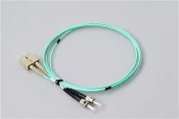
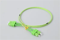
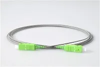
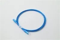
Connector Types
Different applications call for different connectors:
|
Connector |
Size |
Common Applications |
|
LC |
1.25mm ferrule |
Data centers, enterprise networks, high-density |
|
SC |
2.5mm ferrule |
Telecom, FTTH, general purpose |
|
ST |
2.5mm ferrule |
Legacy installations, some industrial |
|
MPO/MTP |
Multi-fiber |
High-bandwidth, parallel optics, 40G/100G+ |
Our fiber optic connectors come in all standard types for both factory and field termination.
Testing and Documentation
Don't skip testing. "The link lights up" doesn't mean the installation is good. A marginal installation might work at 10G but fail at 100G, or work fine in summer but drop out in winter.
Visual Inspection
Before connecting anything, check every connector end face with an inspection microscope at 200-400x magnification. Look for dust, fingerprints, scratches across the core, chips in the ferrule.
Contamination causes most fiber network problems. One industry survey found it's the number one reason for troubleshooting calls. Clean contaminated connectors with proper cleaning tools and re-inspect. Scratches crossing the core area mean the connector needs replacement.
Loss Testing
Optical Loss Test Sets measure total insertion loss end-to-end. Compare measured results against expected loss:
Expected loss = (fiber length × attenuation) + (connectors × 0.3 dB) + (splices × 0.1 dB)
Typical fiber attenuation:
Single-mode at 1310nm: 0.35 dB/km
Single-mode at 1550nm: 0.25 dB/km
Multimode at 850nm: 3.0 dB/km
If measured loss is significantly higher than calculated, something's wrong. Find it before accepting the installation. For premises cabling, TIA-568 standard provides specific loss budgets and testing requirements that most commercial installations should follow.
OTDR Testing
OTDR (Optical Time-Domain Reflectometer) sends light pulses and measures reflections, showing every connector, splice, bend, and fault along the link. The trace tells you exactly where problems are and how severe.
Save OTDR traces for every fiber. When something fails months or years later, comparing current vs original traces shows exactly what changed. Store documentation where future technicians can actually find it-not on someone's laptop that leaves when they change jobs.
Common Problems and Solutions
Link won't establish at all
Check in this order: connectors seated properly? Correct fiber connected (trace it physically)? TX/RX polarity correct? Connectors clean?
Intermittent errors or high bit error rate
Almost always one of three things: contaminated connectors, marginal optical power (link works but no margin), or bend radius violation somewhere in the path. Physically inspect the route looking for tight bends-inside racks, at direction changes, anywhere cable got "stuffed" into a tight space.
Link worked before, now doesn't
Something changed. Was any work done in the area? Did anyone connect or disconnect anything? Compare current OTDR trace to the original baseline.
OTDR shows unexpected high loss at one point
Could be a dirty connector, bad splice, tight bend, or physical damage. Start with cleaning. If that doesn't fix it, physically inspect the location the OTDR identifies.
Conclusion
Good fiber installation comes down to basics: right cable for the environment, careful handling, clean connections, proper testing. Not complicated, but the details matter. Skip them and you'll be troubleshooting problems for years.
Evolux Fiber provides complete fiber optic components-connectors, patch cords, pigtails, adapters, and terminal boxes. Free samples and technical support available for your projects.
Questions about your installation? Contact our team for help.
Related Articles
What Types of Fiber Optic Pigtails Are There?