If you are comparing APC, UPC, and PC fiber connectors, start with the most important distinction: these terms describe the ferrule end-face polish, not the outer connector housing. LC, SC, FC, and ST refer to the physical connector structure. APC, UPC, and PC refer to how the fiber tip inside the ferrule is polished. That is why designations like SC/APC, LC/UPC, or FC/APC are standard - connector type and polish type are two separate properties combined in one product name.
In short: APC (Angled Physical Contact) offers the lowest back reflection and is preferred for reflection-sensitive singlemode systems. UPC (Ultra Physical Contact) delivers strong performance across many general singlemode applications. PC (Physical Contact) is an older polish that has largely been replaced by UPC and APC in current deployments. APC and UPC connectors must never be directly mated to each other.

What Do APC, UPC, and PC Mean in Fiber Connectors?
All three terms belong to the physical-contact connector family. The differences come down to end-face geometry and the resulting optical performance.

PC (Physical Contact) was the first major improvement over early flat-polished fiber connectors. The ferrule end is polished into a slightly curved shape to reduce the air gap between two mated fibers. PC connectors typically achieve a return loss of around −40 dB. While PC was once common on OM1 and OM2 multimode fibers, it is now considered a legacy finish and has been largely replaced by UPC and APC in modern networks. You can learn more about general fiber connector structure to see how ferrule design affects performance.
UPC (Ultra Physical Contact) builds on the PC design with a more refined, dome-shaped end-face polish. The tighter curvature produces better core alignment between mated fibers and improves return loss to approximately −50 dB or better. UPC is the most widely deployed polish type for singlemode fiber connections in enterprise, data center, and general telecom environments.
APC (Angled Physical Contact) takes a different approach. Instead of a flat or rounded finish, the ferrule end face is polished at an 8-degree angle. This angle redirects reflected light into the fiber cladding rather than straight back toward the light source - a critical advantage in applications where back reflection can degrade signal integrity or stress laser equipment. APC connectors routinely achieve return loss of −60 dB or better (see Fluke Networks' APC connector overview for technical details). The SC/APC connector is one of the most common examples of this polish type in the field.
APC vs UPC vs PC: Key Differences at a Glance

| Polish Type | End-Face Geometry | Typical Return Loss | Visual Identification | Primary Applications |
|---|---|---|---|---|
| APC | 8° angled surface | ≈ −60 dB or better | Green connector body | PON/FTTx, WDM, RF video over fiber, CATV |
| UPC | Dome-shaped, ultra-polished | ≈ −50 dB or better | Blue connector body | General singlemode patching, enterprise LAN, digital systems |
| PC | Slightly curved (older finish) | ≈ −40 dB | Varies (beige for multimode, blue for singlemode) | Legacy installations, older multimode hardware |
Note: Exact return loss values vary by connector quality, manufacturer, and test conditions. The figures above reflect widely cited industry references from sources including Fluke Networks and the Fiber Optic Association (FOA). Telcordia GR-326-CORE provides formal test requirements for singlemode connector performance.
APC vs UPC: Return Loss and Back Reflection
Return loss - the amount of light reflected back toward the source at a mated connection - is the most significant practical difference between APC and UPC connectors. It is the reason engineers select one polish over the other.
With a UPC connector, reflected light travels straight back through the fiber core toward the laser or transmitter. For many digital singlemode links, the resulting reflectance (around −50 dB) is manageable. However, in systems that carry analog signals, operate at higher optical wavelengths (above 1500 nm), or run upstream and downstream traffic on a shared fiber - such as PON and WDM architectures - even modest back reflection can cause measurable signal degradation.

APC connectors address this by directing reflected light away from the core and into the cladding, thanks to the 8-degree end-face angle. The result is return loss of −60 dB or better, an order-of-magnitude improvement over UPC on a logarithmic scale. That is why APC is the standard choice for FTTH passive components, RF video overlays, and passive optical LAN designs.
In a typical FTTH distribution panel, for example, many splitter ports remain unconnected until subscriber service is activated. An unmated UPC connector can produce return loss as poor as −14 dB, while an unmated APC connector still maintains reflectance below −50 dB. This is a major reason why service providers standardize on APC for outside plant and PON deployments.
APC vs UPC Insertion Loss: A Common Misunderstanding
A frequent assumption is that APC connectors always produce lower insertion loss than UPC. In practice, that is not quite right. Early APC designs did suffer from higher insertion loss due to alignment challenges at the angled interface. But modern manufacturing processes have effectively closed this gap - current APC and UPC connectors from quality vendors both achieve typical insertion loss in the range of 0.14 dB to 0.18 dB.
The meaningful differentiator is reflectance performance, not insertion loss. If your link budget is built around return loss requirements (as in PON, CATV, or WDM systems), APC is the safer choice. If the link is a straightforward digital singlemode connection without unusual reflectance sensitivity, UPC will serve well.
Color Coding: Green vs Blue Fiber Connectors

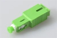
Field identification relies heavily on color. Per the TIA-568 standard, APC connectors use a green body or boot, while UPC connectors use blue. This convention applies across SC connectors, LC connectors, FC connectors, and their associated adapters and patch cords.
Teaching installers and technicians a simple rule - green mates with green, blue mates with blue - is one of the most effective ways to prevent mismatch errors in the field. When working with MPO/MTP connectors, color cues are less reliable, so always verify the label markings for "MPO/UPC" or "MPO/APC."
Can You Connect APC to UPC?

Why Direct Mating Is Not Acceptable
No. APC and UPC connectors must not be directly mated. The angled APC end face and the rounded UPC end face will not align correctly - the fiber cores miss each other, resulting in very high insertion loss and potentially permanent physical damage to the end face. Fluke Networks states explicitly that attempting to mate these two types can damage the connector and the connected transceiver. Even if a technician can physically force an SC/APC connector into an SC/UPC adapter, the optical result will be a failed link.
What to Do When You Need to Bridge APC and UPC
If a design genuinely requires connecting an APC-terminated side to a UPC-terminated side, use a purpose-built hybrid patch cord that has an APC connector on one end and a UPC connector on the other. These cords are factory-assembled so that the polish transition happens at the internal splice or at the far connector - never at the mating interface. Fluke Networks references hybrid UPC-to-APC cords as part of proper test setups for APC-certified links.
The rule is straightforward: match the connector polish to the adapter or port interface. Use a hybrid solution only when the system design explicitly calls for a polish transition.
When to Choose APC Connectors

APC is the preferred polish when the application is sensitive to back reflection. Specific use cases include:
Passive optical networks (PON) and fiber-to-the-home (FTTH) deployments, where PLC splitters create multiple open connector ports that need low reflectance even when unmated. Wavelength-division multiplexing (WDM) systems, where multiple signals share a single fiber and reflected light from one channel can interfere with others. RF video over fiber and CATV distribution, where analog signals are particularly vulnerable to reflection-induced noise. Any link design with multiple connections along a short singlemode span, where cumulative reflections can add up.
In practice, if you are patching a PON splitter port in an FTTH terminal box, the entire path - from OLT to ONU - typically uses SC/APC or LC/APC connectors throughout.
When UPC Connectors Are the Right Choice
UPC connectors work well for general-purpose singlemode patching in environments where back reflection is not the dominant design concern. Typical examples include enterprise LAN fiber runs, standard data center interconnects (1G through 400G Ethernet), digital television and telephony distribution systems, and test-lab patch panels.
Most SFP, SFP+, and QSFP transceivers with LC receptacles are designed for UPC-polished patch cords. Unless the transceiver or port is specifically labeled for APC, UPC is the default assumption for digital Ethernet optics.
Where PC Connectors Still Appear
PC polish is largely a legacy topic. You may still encounter it on older OM1/OM2 multimode equipment, in legacy telecom infrastructure installed before UPC became the default, or in documentation and specifications referencing older fiber standards.
For new deployments, there is rarely a reason to specify PC over UPC. However, understanding PC remains valuable for anyone maintaining or upgrading brownfield fiber plants - if you find beige or older-style connectors on an existing panel, PC is a likely candidate.
How to Choose the Right Fiber Connector Polish

Step 1: Check the Equipment Interface
Start with what the port, transceiver, adapter, or outlet requires. If the device specifies APC, use APC. If it specifies UPC, use UPC. Never try to "upgrade" by guessing a different polish type - direct APC-to-UPC mating will cause problems.
Step 2: Determine Whether the Link Is Reflection-Sensitive
Ask whether reflected light matters in your application. If the link is part of a PON, FTTx, WDM, or RF-video-over-fiber system, APC is almost always the correct answer. If it is a standard digital singlemode connection without unusual reflectance constraints, UPC is typically sufficient.
Step 3: Standardize Across the Link
Do not mix polish types one patch cord at a time. Standardize the polish across the entire connection path - from the patch panel through every jumper and pigtail to the far-end device. Consistent use of color coding (green for APC, blue for UPC) dramatically reduces installation errors during moves, adds, and changes.
Step 4: Verify Before Installation and Testing
Before certifying the link, confirm that your test equipment matches the polish type. APC testing typically requires APC-compatible test reference cords, APC inspection probe tips, and APC adapters. Fluke Networks documents that UPC inspection tips cannot be used to view APC end faces - the angled surface requires a matching probe geometry. Make sure your cleaning and inspection tools are correct for the polish type in use.
SC/APC vs SC/UPC: A Practical Example

The SC connector is one of the most common form factors in fiber optic networks, and the APC-versus-UPC decision comes up frequently in SC-based deployments. An SC/APC fast connector is the standard choice for FTTH drop cable termination - the green body immediately signals that the installer is working within an APC-standardized PON system. An SC/UPC fast connector, on the other hand, fits general-purpose singlemode patching where the network does not demand APC-grade reflectance.
When ordering SC pigtails, patch cords, or adapters, always specify the polish type explicitly. A mismatch between an SC/APC pigtail and an SC/UPC adapter is one of the most common - and most preventable - field errors.
Common Mistakes to Avoid

Confusing connector type with polish type.
LC and SC describe the physical housing. APC and UPC describe the ferrule finish. They answer different questions and must be specified independently.
Assuming APC is universally superior.
APC provides better return loss, but that does not mean every singlemode link needs it. For many digital Ethernet links, UPC delivers excellent performance at lower complexity. Choose based on the application, not a blanket assumption.
Mating green connectors with blue connectors.
This is a field error that causes high loss, failed links, and potential physical damage to the connector end face. Always match green to green and blue to blue.
Overlooking test equipment compatibility.
If you are certifying an APC link, your test reference cords, adapters, and inspection tools all need to match the APC polish. Using UPC test cords on an APC link introduces measurement errors and can damage reference connectors.
Ignoring unmated connector reflectance.
In PON architectures, unused splitter ports are a significant source of back reflection if terminated with UPC connectors. APC connectors maintain low reflectance even when unmated - a critical advantage for networks that scale by activating ports over time.
Frequently Asked Questions
Is APC better than UPC?
Not universally. APC provides superior return loss and is the preferred choice for reflection-sensitive singlemode systems such as PON, WDM, and RF video. UPC remains a strong, widely deployed option for many general singlemode applications where extreme reflectance control is not required.
Can I plug an APC connector into a UPC adapter?
You should not. Directly mating APC to UPC causes poor optical performance and may permanently damage the connector end face. If you need to bridge the two polish types, use a purpose-built hybrid patch cord.
What color is APC vs UPC?
APC connectors are typically green. UPC connectors are typically blue. This color convention follows TIA-568 standards and applies to connector bodies, boots, and adapters.
What does PC mean in fiber connectors?
PC stands for Physical Contact. It is an older ferrule polishing style with a slightly curved end face. PC has been largely superseded by UPC and APC in modern fiber deployments, though it still appears in legacy equipment.
Does APC always have lower insertion loss than UPC?
No. Modern APC and UPC connectors from quality manufacturers achieve comparable insertion loss, typically 0.14 to 0.18 dB. The important distinction is return loss (reflectance), where APC significantly outperforms UPC.
When should I use a hybrid APC-to-UPC patch cord?
Only when your system design genuinely requires bridging an APC interface on one side and a UPC interface on the other. Never create that transition by forcing unlike connectors into a shared adapter.
Can APC connectors be used with multimode fiber?
In practice, APC is almost exclusively used with singlemode fiber. Multimode systems generally use UPC or PC connectors, because multimode applications are less sensitive to back reflection and the 8-degree angle introduces alignment complexity that offers no real benefit for multimode transmission.
Buyer's Quick Checklist
Before placing a connector, patch cord, or pigtail order, run through these checks:
Confirm the port type on both ends of the link - is it APC or UPC? Determine whether the application is reflection-sensitive (PON, FTTx, WDM, RF video). Ensure consistent polish type across the entire connection path: panels, adapters, pigtails, and patch cords. Verify that your inspection and testing tools match the chosen polish. Use color coding consistently - green for APC, blue for UPC - across labeling, documentation, and physical installation.
Following this workflow prevents the most common and most costly installation mistakes. For more information on connector selection for specific applications, see our guides on fiber connector polish types and fast connectors vs fusion splicing.