Every fiber-to-the-home project lives or dies by its passive optical components. The active equipment - OLTs, ONTs, switches - gets most of the attention during planning, but the Optical Distribution Network (ODN) sitting between them is where signal quality, maintenance cost, and long-term scalability are actually determined. For telecom operators and ISPs rolling out GPON or XGS-PON networks, understanding each passive component in the ODN chain is not optional - it is the difference between a network that runs for 25 years and one that generates trouble tickets from day one.
This guide walks through the six core passive fiber optic components that make up a modern FTTH deployment, explains where each one sits in the network, and highlights the specifications that matter most when you are writing a purchase order.
How the ODN Links Everything Together
A typical FTTH passive optical network follows a straightforward path: the OLT at the central office sends optical signals through trunk fiber cables to one or more splitting stages, which distribute the signal to individual subscribers. Between the OLT port and the subscriber's ONT, every connection, split, and termination point relies on passive components working in concert.
Think of the ODN as a chain. The weakest link - a poorly polished fiber optic connector, a mismatched adapter, or an undersized splitter - defines the performance ceiling for the entire network. That is why procurement decisions at the component level have outsized impact on network-level outcomes.
Fiber Optic Connectors: The Foundation of Every Link
Connectors are the most frequently handled components in any fiber network. In FTTH, fiber optic connectors appear at the OLT patch panel, inside distribution cabinets, at splitter interfaces, and at subscriber terminal points. Getting the connector type right at each location avoids rework, minimizes insertion loss, and keeps your optical power budget intact.
SC/APC connectors remain the standard for FTTH access networks worldwide. The 8-degree angled polish delivers return loss better than −60 dB, which is critical for PON systems that are highly sensitive to back-reflection. You will find SC/APC interfaces on most PLC splitters, ODF panels, and drop cable assemblies designed for last-mile deployment.
LC connectors dominate in high-density environments like central offices and data centers. Their 1.25 mm ferrule - half the size of an SC - allows significantly more ports per rack unit. For ISPs managing thousands of OLT ports, LC-based patching directly translates to space and cost savings.
MPO/MTP connectors are becoming essential for trunk cabling between central offices and distribution points. A single MPO connector carrying 12 or 24 fibers replaces a bundle of individual patch cords, dramatically accelerating deployment speed and simplifying cable management in high-fiber-count routes.
What to specify: Always confirm the polish type (APC vs. UPC), insertion loss (target <0.2 dB), return loss (>50 dB for UPC, >60 dB for APC), and ferrule material (zirconia ceramic is the industry benchmark for single-mode applications).
Fiber Optic Adapters: The Silent Alignment Engines
Every time two connectors meet inside an ODF, a splice closure, or a terminal box, a fiber optic adapter is doing the critical work of aligning the two ferrules with micron-level precision. Adapters are often overlooked during procurement, but a low-quality adapter with a worn alignment sleeve can add 0.3–0.5 dB of unexpected loss per mating - enough to push a marginal link out of spec.
For FTTH projects, SC/APC simplex adapters are the workhorse. They mount into distribution frames, terminal boxes, and splitter enclosures throughout the ODN. In central office environments where LC patching is used, LC duplex adapters provide the density needed for high-port-count OLT chassis.
Hybrid adapters - such as SC-to-LC or FC-to-SC - solve a common pain point when legacy equipment must coexist with newer infrastructure. Rather than replacing entire patch cord inventories, a hybrid adapter bridges the gap at minimal cost.
What to specify: Alignment sleeve material (zirconia or bronze), additional insertion loss (<0.1 dB), mounting type (panel-mount, bulkhead, or snap-in), and durability rating (minimum 500 mating cycles for field-deployed adapters, 1000+ for central office use).
Fiber Optic Pigtails: Factory Precision at Every Termination
A fiber optic pigtail is a short length of fiber with a factory-polished connector on one end and bare fiber on the other. Inside an ODF or terminal box, the bare end is fusion spliced to a trunk cable fiber, and the connector end plugs into an adapter on the panel front. This is how raw cable fibers become patchable, manageable ports.
Why not just field-terminate connectors directly onto trunk fibers? Because factory-controlled ferrule geometry - end-face radius, apex offset, fiber protrusion - delivers insertion loss and return loss numbers that are nearly impossible to replicate consistently in the field. For GPON networks operating on tight optical budgets over 20 km splits, that consistency is not a luxury. It is a requirement.
SC/APC pigtails in single-mode OS2 fiber are the default choice for FTTH access networks. Standard lengths of 1 m to 1.5 m fit most ODF and terminal box enclosures. LC/UPC pigtails are common in central office ODFs where LC-based OLT patching is used. For multi-fiber trunk breakout, ribbon pigtails (6-fiber or 12-fiber) reduce splicing time significantly in high-fiber-count deployments.
What to specify: Connector type and polish, fiber type (OS2 single-mode for virtually all FTTH), jacket material (LSZH is mandatory in most indoor applications), length, and color coding for easy identification.
Fiber Optic Patch Cords: The Flexible Connections
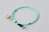
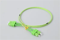
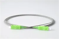
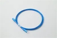
Where pigtails provide permanent, spliced connections, fiber optic patch cords deliver the flexibility that operators need for day-to-day patching, provisioning, and troubleshooting. A patch cord has factory-polished connectors on both ends and plugs into adapters on either side of the link.
In FTTH networks, patch cords appear in two key locations. At the central office, they connect OLT ports to ODF panels - typically LC-to-LC or LC-to-SC configurations. At the subscriber end, a short SC/APC-to-SC/APC drop patch cord links the terminal box to the ONT.
For operators deploying high-speed 40G or 100G links within central offices, MPO trunk patch cords and MPO-to-LC breakout cables are becoming standard. These multi-fiber assemblies connect high-port-count OLT line cards to distribution frames in a single cable run, reducing congestion and simplifying moves-adds-changes.
What to specify: Connector combination, fiber type and grade, cable diameter (2.0 mm or 3.0 mm for standard, 0.9 mm for high-density), jacket rating (LSZH, OFNP, or armored for exposed routes), and insertion loss per connector (<0.3 dB).
PLC Splitters: The Heart of PON Architecture
The fiber optic PLC splitter is arguably the most strategically important passive component in an FTTH network. It takes a single optical input from the OLT and divides it among multiple subscribers - typically in ratios of 1:8, 1:16, 1:32, or 1:64 for GPON deployments.
Planar Lightwave Circuit (PLC) technology is preferred over older Fused Biconic Taper (FBT) designs for split ratios above 1:4 because PLC splitters deliver superior uniformity across all output ports and support the full wavelength range (1260–1650 nm) required by GPON, XGS-PON, and RF video overlay.
Splitter placement strategy directly affects your network economics. A centralized split model (one 1:32 or 1:64 at the central office) minimizes the number of splitter locations but requires more fiber in the distribution network. A cascaded split model (1:4 at a cabinet, then 1:8 at a distribution box) reduces trunk fiber counts but adds more splice and connection points. Most operators use a combination, optimized for their specific subscriber density and geography.
PLC splitters come in several form factors - bare fiber, mini steel tube, ABS box, LGX cassette, and rack-mount tray. The right packaging depends on where the splitter is installed. ABS box splitters fit neatly inside outdoor fiber distribution terminals. LGX cassettes slide into standard 19-inch rack frames at the central office. Mini modules work well inside compact splice closures along the distribution route.
What to specify: Split ratio, connector type (SC/APC is standard), packaging type, operating wavelength range, insertion loss per port (check both maximum and uniformity), and operating temperature range (especially for outdoor cabinet deployment).
Fiber Optic Terminal Boxes: The Last Meter
The fiber optic terminal box is where the passive network meets the subscriber. Mounted on an exterior wall, inside a building corridor, or at a desk-side outlet, the terminal box provides a protected environment for the final splice and connector interface between the drop cable and the subscriber's patch cord to the ONT.
A well-designed terminal box integrates fiber routing channels that maintain minimum bend radius (typically 30 mm for standard fiber, 15 mm for bend-insensitive), a splice tray for securing the pigtail-to-drop-cable fusion splice, and one or more adapter ports for the subscriber connection. Capacity ranges from single-port residential rosettes to 24-port wall-mount enclosures for multi-dwelling units (MDUs).
For outdoor deployments, look for IP65-rated enclosures with UV-resistant housings. For indoor residential installations, compact fiber rosette boxes with integrated SC/APC adapters provide a clean, professional endpoint that subscribers can understand and respect.
What to specify: Port count, mounting style (wall-mount, desk-mount, or DIN-rail), adapter type pre-loaded, ingress protection rating, splice tray capacity, and cable entry configuration (top, bottom, or side).
Building a Smarter FTTH Bill of Materials
The most common procurement mistake in FTTH projects is specifying each component in isolation. Connectors, adapters, pigtails, patch cords, splitters, and terminal boxes are not independent purchases - they form an integrated optical chain where every interface must be physically and optically compatible.
Before issuing purchase orders, map your network design end-to-end: OLT port → ODF (pigtails + adapters) → trunk cable → splitter (connectors + packaging) → distribution cable → terminal box (adapter + pigtail splice) → drop patch cord → ONT. At every node, confirm that connector types match, polish types are consistent (do not mix APC and UPC in the same link), and your cumulative insertion loss stays within the optical power budget.
Working with a manufacturer that supplies the full range of FTTH passive components - from connectors and adapters to PLC splitters and terminal boxes - reduces the risk of compatibility issues, simplifies logistics, and often unlocks better pricing through consolidated orders. It also means one point of contact for technical support when field issues arise, rather than finger-pointing between five different suppliers.
Your passive components will outlast multiple generations of active equipment. Specify them carefully, source them from a partner who understands the complete ODN chain, and your FTTH network will deliver reliable broadband for decades to come.
Evolux Fiber provides a complete range of FTTH passive optical components - including fiber optic connectors, adapters, pigtails, patch cords, PLC splitters, and terminal boxes - serving telecom operators and ISPs in over 50 countries. Contact us for customized FTTH component solutions and competitive project pricing.