A few months ago, a logistics company in Shenzhen asked us to look at a fiber link that had been giving them grief - random CRC errors on a 10G uplink between two buildings, maybe twice a day, never at the same time. Their network vendor had already swapped out the SFP+ modules and replaced the media converter. No improvement. When we got on-site and pulled the SC connector at the ODF, the end face looked clean to the naked eye. Under a 400x microscope, there was a ring of residue around the core - probably leftover polishing compound from the original termination, never cleaned. A thirty-second wipe with a one-click cleaner, re-mate, and the errors stopped. That connector had been in place for two years.
We see variations of this scenario constantly. After a decade in the fiber optic component business, the lesson that keeps repeating itself is that most fiber network failures aren't complicated - they're just hard to see. This guide is the diagnostic framework we walk customers through when they call us with fiber issues, organized from the simplest check to the most involved.

First, Forget Everything You Know About Copper
If your background is in copper networking, fiber troubleshooting requires a reset. With copper, failures tend to leave obvious evidence - EMI shows up on a spectrum analyzer, crosstalk produces measurable near-end noise, and a damaged cable is usually visibly damaged. Fiber doesn't give you those cues. A contaminated end face looks fine without magnification. A stressed cable might pass a visual inspection but introduce loss only when the building HVAC cycles the temperature. The failure modes are subtler, and the diagnostic tools are different.
The core concept is straightforward, though: you are tracing the path of light, and looking for anywhere that light is leaking, scattering, or reflecting instead of reaching the receiver. Once that framework clicks, the rest follows logically.
The Usual Suspects: Five Issues That Account for 90% of Fiber Failures
1. Connector Contamination - The Problem Nobody Takes Seriously Enough
We're putting this first because it causes more unnecessary downtime than everything else on this list combined. A single dust particle on a connector end face - 1 micron, invisible without magnification - can push insertion loss from 0.3 dB to well over 1.5 dB, enough to crash a high-speed link. The Shenzhen case in our opening was typical: a connector that had never been inspected since installation, accumulating contamination for two years while everyone assumed the hardware was the problem.
New connectors get contaminated too. Shipping, handling, even the act of removing a dust cap in a non-cleanroom environment can deposit particles. That's why the only reliable policy is inspect-before-you-mate, every single time. Use a fiber inspection microscope at 200x minimum - we evaluate against the IEC 61300-3-35 pass/fail standard - and clean with a one-click cleaner for SC and LC connectors, or 2.5mm/1.25mm cleaning sticks for adapter ports. Our cleaning guidelines for fiber optic jumpers walk through the full dry-then-wet protocol.
2. Signal Loss (Attenuation)
Beyond connector contamination, attenuation has deeper roots. Some loss is intrinsic - Rayleigh scattering within the glass itself, absorption by trace impurities - and there's nothing you can do about it except account for it in your link budget. The losses you can fight are extrinsic: bad splices, misaligned ferrules, excessive bending, or - a classic mistake - mating a single-mode pigtail to a multimode patch cord.
Here's how we attack it in the field. We measure the link end-to-end with an optical power meter at both 1310nm and 1550nm. If the total loss exceeds the design budget, we segment the link and test section by section until we isolate which span is eating the margin. Nine times out of ten it's a connector that needs recleaning or a splice point with higher loss than the original installation records claimed. If your patch cords are sourced from different vendors, pay extra attention - we've seen insertion loss vary by 0.3 dB or more between suppliers on connectors that are nominally identical.
3. Fiber Breaks
Breaks are dramatic but at least they're definitive. The link goes down completely, or the OTDR trace shows a sharp event with massive return loss at a specific distance. The causes are what you'd expect: construction work, rodent damage, someone yanking a cable instead of pulling it properly.
But here's one that catches people off guard: delayed stress fractures. A technician routes a jumper behind a panel with a tight bend during installation. It passes light fine on day one. Then seasonal temperature changes cause the jacket to contract, the glass reaches its stress threshold, and the fiber snaps at 2 AM on a Saturday. We see this regularly in outdoor and semi-outdoor terminal boxes that experience thermal cycling.
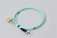
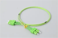
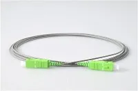
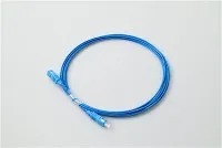
For diagnosis, a Visual Fault Locator (VFL) is your fastest tool - the red laser light escapes through the jacket at the break point and is visible even under normal lighting. For inaccessible trunk runs, OTDR pinpoints the fault distance precisely. As for repair: if it's a patch cord or jumper, don't waste time - replace it. Patch cords cost a few dollars; the labor to splice one costs ten times that and produces an inferior result. Fusion splicing (typically under 0.05 dB loss) is reserved for trunk cables and permanent plant where replacement isn't practical. In emergency field situations, mechanical splicing gets you back online quickly, but plan to replace it with a proper fusion splice during the next maintenance window.
4. Dispersion: When the Link Tests Fine but the Data Doesn't
Here's a scenario that confuses a lot of technicians. A long-haul single-mode link passes every optical power test with comfortable margin, but the switch logs are full of FCS errors. Or an existing campus backbone works flawlessly at 1G, gets upgraded to 10G with new transceivers, and the BER goes through the floor - with no physical changes to the fiber plant at all.
The culprit is usually dispersion. Chromatic dispersion occurs because the laser source isn't perfectly monochromatic - it contains a narrow spread of wavelengths that travel through glass at slightly different velocities. Over short distances this doesn't matter. Over 40+ km of single-mode fiber, or at data rates where pulse widths become very narrow (10G and above on longer spans), the accumulated broadening causes adjacent pulses to overlap. On multimode fiber, modal dispersion adds another layer - light physically takes different paths through the larger core, arriving at the receiver at different times.
Addressing chromatic dispersion on long single-mode runs starts with verifying the fiber spec - G.652.D fiber has significantly better dispersion characteristics than older G.652.A/B plant. For existing infrastructure where the fiber can't be replaced, Dispersion Compensating Fiber (DCF) modules inserted at amplification points can recover the link. Modal dispersion on multimode is fundamentally a distance-versus-bandwidth limitation; if you're hitting the ceiling, the real answer is a migration path from multimode to single-mode, or at minimum upgrading from OM3 to OM4/OM5 multimode to buy additional headroom.
5. The Polarity Trap in High-Density MPO/MTP Systems
This one doesn't show up in most troubleshooting guides, but it should. As data centers move toward 40G and 100G using MTP/MPO connectivity, polarity management becomes a real troubleshooting challenge. MPO connectors carry 8, 12, or 24 fibers in a single ferrule, and the fiber mapping between the "key up" and "key down" orientation must match on both ends of the link for each transmit/receive pair to align correctly.
Mix patches from different vendors - or worse, mix Type A, B, and C polarity cables without tracking which is which - and you'll get links that either fail completely or experience bizarre intermittent behavior as some fiber pairs connect properly and others don't. We've seen network teams spend days chasing what they thought was a transceiver problem, only to discover that a single MPO trunk cable had been flipped. The fix is straightforward (swap the polarity or use the correct adapter), but finding the problem without systematic polarity testing can burn enormous amounts of time.
A Troubleshooting Workflow That Actually Works
Random testing is expensive and demoralizing. Here's the escalation path we recommend, ordered by cost and complexity so you're not reaching for an OTDR when a cleaning wipe would have solved it.
Step 1: Eyes first. Walk the cable path. Look for obvious damage, sharp bends, disconnected jumpers, missing dust caps. Check near cable trays, floor penetrations, and any area where recent construction or maintenance occurred. You'd be amazed how often "the network is down" translates to "someone unplugged something."
Step 2: Inspect and clean every connector in the suspect path. Pull each connection. Microscope. Clean. Re-mate. This alone resolves the majority of issues we see in the field.
Step 3: Measure optical power. If cleaning didn't fix it, bring in a calibrated light source and power meter. Measure insertion loss segment by segment. Compare each measurement against the link loss budget from the original installation documentation. Any segment that exceeds its budget by more than 0.5 dB deserves closer investigation.
Step 4: OTDR for the hard cases. When segment-level testing points to a mid-span fault - something between connectors that you can't access visually - the OTDR maps the entire fiber run. It shows you exactly where the event is, what type it is (reflective vs. non-reflective), and how much loss it's causing. One note: match your OTDR pulse width to the link length. Too narrow a pulse and you lose range; too wide and you can't distinguish closely spaced events.
Step 5: Environmental check. If every optical parameter looks clean but the problem persists intermittently, consider environmental factors. Temperature fluctuations can cause micro-bending in improperly secured cables. Humidity can degrade connectors over time. Vibration from nearby HVAC or industrial equipment can loosen mechanical splices. We've even seen issues traced to cleaning crews bumping fiber trays during after-hours maintenance. Check your enclosure seals - if moisture is getting in, your splice points are degrading faster than you think.
Keeping Your Network Off the Troubleshooting Table
The best troubleshooting session is the one you never have to do. Preventive maintenance isn't glamorous, but the math is hard to argue with: a scheduled cleaning visit costs a fraction of an emergency after-hours truck roll.
The foundation is a "clean before connect" policy, enforced without exceptions. Beyond that, run OTDR baseline scans after every new installation and save the traces. When a problem surfaces six months later, you can overlay the current trace against the baseline and instantly see what changed - instead of guessing. For high-change environments like colo data centers, we recommend quarterly re-baselines.
Cable management matters more than most teams acknowledge. Every fiber run should respect the manufacturer's minimum bend radius - typically 10x the cable diameter, or about 15mm for most bend-insensitive G.657.A2 fiber. If your installation doesn't use proper routing hardware, the day will come when someone pushes a new cable through a tray and creates a macro-bend on three existing ones. Take the time to organize pigtail routing and install strain relief at every termination point - it pays for itself the first time you avoid a thermal-cycle break.
Finally, track your optical power budget over time. Networks evolve - PLC splitters get added, patch cords get swapped, new equipment introduces different receiver sensitivities. If your margin was 3 dB at installation and it's now 0.8 dB, you're one dirty connector away from an outage. A semiannual power meter audit takes an afternoon and can save you from waking up to a 3 AM alert.
When It's Time to Call for Backup
Not every problem is a DIY project. If your OTDR traces show anomalies you can't explain, if intermittent errors don't correlate with any measurable optical parameter, or if a critical link requires fusion splicing and you don't have a certified splicer on staff - bring in a specialist. The cost of a bad splice, in terms of both wasted fiber and extended downtime, always exceeds the cost of doing it right the first time.
Evolux Fiber has been supplying connectors, patch cords, splitters, and related components to network teams across 30+ countries. If you're dealing with a fiber issue and could use a second opinion, reach out to our engineering team - sometimes talking through the symptoms with someone who's seen the same problem a hundred times is the fastest path to a fix.