PLC Splitter: What It Is, How It Works, and How to Choose the Right One for Your Network
A PLC splitter (Planar Lightwave Circuit splitter) is a passive optical component that divides a single optical signal into multiple output signals without requiring electrical power. In fiber access networks built on optical splitter technology, PLC splitters serve as the core distribution element - allowing one feeder fiber from the central office to reach dozens of subscribers through a compact, reliable device.
For engineers planning an FTTH rollout or buyers comparing splitter options for a PON project, the key questions are often the same: which split ratio fits the network, what package type works for the enclosure, and whether PLC or FBT is the better choice. This guide covers those questions in detail - with practical selection criteria, comparison data, and deployment considerations drawn from real-world fiber access scenarios.

What Is a PLC Splitter and How Does It Work?
PLC stands for Planar Lightwave Circuit. Unlike older fused-fiber approaches, a PLC splitter is fabricated using silica-based optical waveguide technology on a flat substrate - a process sometimes compared to semiconductor lithography. The incoming optical signal enters through the input port, travels along a precisely etched waveguide structure, and is divided into multiple output paths. Common configurations include 1x2, 1x4, 1x8, 1x16, 1x32, and 1x64.

Because it is a passive device, a PLC splitter requires no external power source. Signal distribution happens entirely through the optical waveguide - which is one reason PLC splitters are favored in access networks where long-term reliability and minimal maintenance matter. The waveguide design also allows PLC splitters to operate across a wide wavelength range, typically covering 1260 nm to 1650 nm, which means a single splitter can handle upstream, downstream, and video overlay wavelengths simultaneously in a GPON or XGS-PON deployment.
Why Uniform Output Matters in Practice
In a multi-user fiber network, each subscriber's optical network terminal (ONT) needs to receive a signal strong enough to maintain reliable service. If splitter outputs vary significantly, some users may experience degraded performance while others have excess margin - complicating link budget planning and future troubleshooting. PLC splitters are designed to keep output uniformity within a tight range (typically less than 1.5 dB variation between ports for a 1x32 unit), which simplifies power budgeting across all connected endpoints.
Why PLC Splitters Are the Standard Choice in PON and FTTx Networks
Passive optical networks rely on splitters to share a single OLT (Optical Line Terminal) port among multiple subscribers. In the ITU-T G.984 GPON standard, the optical distribution network (ODN) between the central office and subscriber side is composed entirely of passive elements - fibers, splitters, and connectors. PLC splitters are the most widely deployed splitter type in this architecture because they support the split ratios (up to 1x64 in common practice) and wavelength ranges that GPON, EPON, and XGS-PON systems require.

In a typical FTTH deployment, a PLC splitter is placed either in a central office rack, an outdoor fiber distribution cabinet, or a building-level fiber distribution box - depending on the network topology and subscriber density. The goal is not just to split the signal, but to do it in a location that balances fiber routing efficiency, enclosure space, and ease of future maintenance. For operators building out residential access networks, a 1x32 PLC splitter in the distribution layer is a common baseline - though the actual ratio depends on subscriber count, distance, and link budget constraints.
PLC Splitter vs. FBT Splitter: A Practical Comparison
The choice between PLC and FBT (Fused Biconical Taper) splitters is one of the most common questions in fiber network procurement. Both are passive optical splitters, but they differ in fabrication method, performance characteristics, and ideal use cases. The following table summarizes the key differences based on industry-standard specifications.

| Parameter | PLC Splitter | FBT Splitter |
|---|---|---|
| Fabrication method | Silica waveguide on planar substrate | Fused optical fibers |
| Operating wavelength | 1260–1650 nm (wideband) | Typically 850, 1310, 1550 nm only |
| Split ratio range | 1x2 to 1x64 (and beyond via cascade) | Best suited for 1x2 to 1x8 |
| Output uniformity | High - consistent across all ports | Decreases at higher split ratios |
| Operating temperature | –40°C to +85°C (typical) | Narrower range; performance affected outside spec |
| Size at high port count | Compact | Larger (requires cascading) |
| Cost for low splits (1x2, 1x4) | Higher | Lower |
| Cost-effectiveness at 1x16+ | Better overall value | Higher loss, less reliable |
| Uneven split ratios (e.g., 10/90) | Not standard | Available |
| Reliability certification | Telcordia GR-1209 / GR-1221 compliant | Available but less common at high splits |
When to Choose PLC Over FBT
For structured FTTH and PON deployments where the split ratio is 1x8 or higher, PLC splitters are generally the more practical choice. They offer better output uniformity, wider wavelength compatibility, and more predictable long-term performance - especially in environments with temperature variation. According to testing criteria defined in Telcordia GR-1209-CORE, PLC splitters must demonstrate stable insertion loss under mechanical and environmental stress, which supports their use in both indoor and outdoor enclosures.
When FBT May Still Make Sense
FBT splitters remain a reasonable option for simple, low-ratio applications - for example, a 1x2 or 1x4 split in a short-reach monitoring tap or a cost-sensitive point-to-point link. They also support uneven split ratios (such as 20/80 or 10/90), which PLC splitters do not typically offer. However, buyers should be cautious about using FBT splitters beyond 1x4 in production networks, as uniformity and reliability degrade at higher port counts.
Common PLC Splitter Types and Package Formats
Choosing a PLC splitter involves more than selecting a split ratio. The package format determines how the splitter integrates into the physical network infrastructure - including enclosures, splice trays, and distribution frames.

1xN and 2xN Configurations
A 1xN PLC splitter has one input and N outputs. This is the standard format for most fiber distribution scenarios. A 2xN PLC splitter provides two inputs, which allows for path redundancy or dual-source architectures - a design sometimes specified in carrier-grade networks or projects that require protection switching at the splitter level.
Bare Fiber and Mini Tube PLC Splitters
These are compact, unpackaged forms where the splitter chip is protected by a steel tube with bare fiber pigtails on both sides. They are often used inside splice closures, distribution boxes, or OEM assemblies where space is tight and the splitter will be further protected by an external enclosure. In FTTH builds that use pre-connectorized drop cables and small terminal boxes, bare fiber splitters help keep the overall footprint minimal.
ABS Box PLC Splitters
ABS box packaging encloses the splitter in a compact plastic housing with fiber pigtails routed out from both ends. This format offers moderate protection and is widely used in general-purpose deployments - from distribution cabinets to wall-mounted boxes. It is also the most common choice when the installation does not follow a standardized rack or panel framework.
LGX Cassette PLC Splitters
LGX (Lightguide Cross-Connect) cassettes are designed to fit into standard 19-inch rack panels and fiber distribution frames. When fiber management needs to be organized by port and clearly labeled, an LGX cassette splitter provides a structured, modular approach. This is a frequent choice in central office environments and multi-tenant building basements where ODF or patch panel systems are already in place.
Rack-Mount PLC Splitters
For high-density deployments in data rooms, central offices, or large-scale PON head-ends, rack-mount PLC splitters integrate directly into a 1U or 2U chassis. This format supports organized cable routing, front-panel access for patching, and easier identification of individual splitter ports during maintenance.
Connectorized vs. Unconnectorized
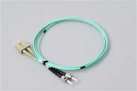
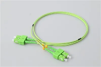
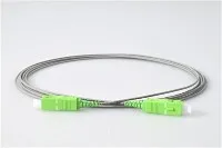
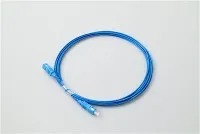
PLC splitters are available with factory-installed fiber optic connectors (such as SC/APC, LC/UPC, or FC/APC) or with bare fiber ends for field splicing. Connectorized models simplify installation and reduce on-site labor - particularly useful in large-scale deployments where speed matters. Unconnectorized splitters offer more flexibility when the termination standard varies across different parts of the network.
How to Choose the Right PLC Splitter for Your Deployment
Selecting a PLC splitter for a real project starts with the network architecture - not the product catalog. The split ratio, package type, connector format, and installation environment all need to align with the deployment plan. Below is a structured approach that covers the most critical decision points.

Step 1: Determine the Split Ratio Based on Network Design
The split ratio defines how many output ports the splitter provides - and directly impacts the optical power available at each endpoint. Every doubling of the split count adds approximately 3 dB of loss per port. The following table provides a quick reference for matching split ratios to common deployment scenarios.
| Split Ratio | Typical Max Insertion Loss | Common Deployment Scenario |
|---|---|---|
| 1x4 | ≤ 7.4 dB | Small branch networks, monitoring taps, rural extensions |
| 1x8 | ≤ 10.7 dB | Small residential clusters, building-level distribution |
| 1x16 | ≤ 13.8 dB | Medium-density residential, campus or MDU access |
| 1x32 | ≤ 16.8 dB | Standard FTTH PON distribution, urban residential |
| 1x64 | ≤ 20.5 dB | High-density urban deployment with short reach |
Note: Insertion loss values above represent typical maximum specifications for PLC splitters. Always use the maximum values from the manufacturer's datasheet when calculating link budgets. Connector loss (typically 0.3 dB per mated pair) adds to the total.
Do not select the highest split ratio just because the project may grow. A 1x64 split consumes significantly more link budget than a 1x32, which limits reach distance and leaves less margin for connector aging and fiber bends. In practice, many operators deploy 1x32 as the default for GPON FTTH, reserving 1x64 for short-reach, high-density areas where the OLT-to-subscriber distance is under 10 km.
Step 2: Choose the Package Type Based on Installation Environment
The package format needs to match the physical infrastructure where the splitter will be installed. Mismatched packaging is a common source of installation delays - a splitter that does not fit the tray, enclosure, or frame means field rework.
| Installation Environment | Recommended Package Type | Notes |
|---|---|---|
| Splice closure or small distribution box | Bare fiber / Mini tube | Minimal footprint; protected by external enclosure |
| Wall-mount or pole-mount cabinet | ABS box | Flexible mounting; moderate protection |
| ODF, patch panel, or 19-inch rack | LGX cassette | Standardized form factor; organized port access |
| Central office or data room | Rack-mount (1U/2U) | High density; front-panel patching |
| Outdoor cabinet or harsh environment | ABS box or sealed enclosure | Verify IP rating and temperature spec for outdoor use |
Step 3: Confirm Connector and Fiber Requirements
Before placing an order, verify these details against the network design and existing infrastructure:
- Connector type - SC/APC is the most common choice for FTTH PON networks; LC/UPC is often used in data center or high-density panel environments. Match the connector to the fiber optic adapters already installed in the enclosure.
- Polish type - APC (angled physical contact) is standard for PON because it provides higher return loss, which is critical for analog video overlay and sensitive transmission. UPC is used in some enterprise or test setups. Mixing APC and UPC connectors on the same link will cause high loss and potential equipment damage. For a detailed comparison, see the guide on PC vs. UPC vs. APC polish types.
- Fiber type - Most PLC splitters use G.657.A1 or G.657.A2 single-mode fiber, which offers improved bend performance over standard G.652D. Confirm this matches the fiber type used in the rest of the network.
- Cable length - If ordering a connectorized splitter, specify the pigtail length needed for routing within the enclosure. Excess cable creates management problems; too little cable prevents proper patching.
Step 4: Plan for Expansion and Maintenance
A splitter is a long-lived infrastructure component. In structured FTTH deployments, buyers often evaluate not just the immediate subscriber count, but also future growth potential, enclosure compatibility for additional modules, and ease of port identification during fault isolation. Choosing a modular package format (such as LGX cassettes) and leaving spare capacity in the distribution frame simplifies future splitter additions without disrupting existing connections.
PLC Splitter Applications Beyond FTTH

While FTTH and PON represent the largest market for PLC splitters, the technology is used across several other fiber distribution scenarios.
GPON, EPON, and XGS-PON Access Networks
PLC splitters are a fundamental element of the ODN in all major PON standards. In a GPON system compliant with ITU-T G.984.3, the splitter sits between the OLT and up to 64 ONUs, distributing downstream broadcast traffic and combining upstream bursts. The same physical splitter infrastructure supports EPON (IEEE 802.3ah) and next-generation XGS-PON (ITU-T G.9807.1) deployments - an important consideration for operators planning technology upgrades on existing ODN fiber plants.
CATV and RF-over-Fiber Distribution
PLC splitters are also used in CATV overlay systems where a 1550 nm video signal is combined with GPON data wavelengths and distributed over the same fiber. The splitter's wideband operating range (covering 1550 nm alongside 1310 nm and 1490 nm) allows it to handle all three wavelengths without requiring separate splitting stages.
Multi-Dwelling Unit (MDU) and Campus Networks
In MDU cabling projects, PLC splitters are often deployed inside building basements or floor-level distribution points to serve multiple apartments from a single feeder fiber. A well-designed MDU cabling plan considers splitter placement, enclosure size, and the number of floors served per splitter to minimize fiber runs and simplify subscriber activation.
Fiber Monitoring and Test Access
Low-ratio PLC splitters (1x2 at 1/99 or 5/95 ratios, where available, or standard 1x2 for equal splits) are sometimes used as monitoring taps in network segments that require continuous optical performance monitoring without disrupting live traffic.
Common Mistakes to Avoid When Buying PLC Splitters

Even experienced procurement teams encounter issues that could be avoided with better upfront specification. Here are the most frequent problems seen in fiber access projects:
- Selecting split ratio without checking link budget. A 1x32 splitter introduces roughly 17 dB of loss at the splitter alone. If the total path loss (including fiber attenuation, connector loss, and splitter loss) exceeds the OLT/ONT power budget, subscribers at the far end will experience service degradation. Always calculate the complete link budget before finalizing the split ratio.
- Ignoring enclosure compatibility. An LGX cassette that does not fit the existing patch panel tray, or an ABS box too large for the distribution box, creates unnecessary rework. Request enclosure dimensions and tray specifications before ordering.
- Mixing APC and UPC connectors. This is one of the most common field errors. An SC/APC connector mated with an SC/UPC adapter causes high insertion loss and poor return loss - and may damage the fiber end face. Standardize the polish type across the entire ODN link.
- Overlooking environmental ratings for outdoor use. A splitter rated for indoor use may not survive temperature cycling, humidity, or UV exposure in an outdoor cabinet. For outdoor or semi-outdoor installations, verify the operating temperature range and confirm compliance with environmental testing standards such as Telcordia GR-1209 and GR-1221.
- Buying on unit price alone. A lower-cost splitter with higher insertion loss or wider output variation can cost more in the long run through additional troubleshooting, reduced reach, and premature replacement. Evaluate total cost of ownership, not just piece price.
PLC Splitter Selection Checklist
Before finalizing a purchase order, confirm the following items against your network design and site conditions:
- Split ratio matches subscriber count, growth plan, and link budget calculation
- Package type fits the target enclosure or distribution frame
- Connector type and polish (APC/UPC) are consistent with existing ODN components
- Fiber type (G.657.A1, G.657.A2, or G.652D) matches the network standard
- Pigtail cable length is specified for the enclosure routing path
- Operating temperature range covers the installation environment (indoor, outdoor, or mixed)
- Supplier provides test reports showing insertion loss, uniformity, and return loss per unit
- Splitter meets applicable reliability standards (Telcordia GR-1209-CORE, GR-1221-CORE, or equivalent)
Frequently Asked Questions
What is the difference between a PLC splitter and an optical splitter?
An optical splitter is a broad category of passive devices that divide optical signals. PLC and FBT are the two main types. A PLC splitter uses waveguide technology for consistent performance across a wide wavelength range, while an FBT splitter uses fused fibers and is better suited for low-ratio, single-wavelength applications.
What split ratio should I choose for a PLC splitter in an FTTH project?
In most GPON-based FTTH deployments, a 1x32 split ratio is the standard starting point. For smaller clusters or rural extensions, 1x8 or 1x16 may be sufficient. For high-density urban areas with short OLT-to-subscriber distances, 1x64 can be considered - but only if the link budget supports it. The decision should always be validated through a power budget calculation that accounts for fiber length, connector count, and splitter loss.
Can PLC splitters support XGS-PON and 10G-PON upgrades?
Yes. Because PLC splitters operate across a wide wavelength range (1260–1650 nm), the same physical splitter deployed for GPON can support XGS-PON (which uses different downstream/upstream wavelengths) without replacement. This is a key advantage of PLC technology for operators planning technology migration on existing fiber plants.
What connector type is most common for PLC splitters in PON networks?
SC/APC is the dominant connector type for FTTH and PON applications. The angled polish provides higher return loss, which is important for systems carrying analog video overlay signals. In enterprise or data center environments, LC/UPC is more common due to its smaller form factor and higher port density. For a full overview, see the fiber optic connector types guide.
How do I calculate the total link loss when using a PLC splitter?
Total link loss is the sum of fiber attenuation (typically 0.35 dB/km at 1310 nm for single-mode fiber), connector loss (approximately 0.3 dB per mated pair), splice loss (approximately 0.1 dB per fusion splice), and splitter insertion loss (refer to the manufacturer's maximum specification). The total must fall within the transmitter-to-receiver power budget defined by the PON standard - for example, GPON Class B+ allows a maximum ODN loss of 28 dB.
Can PLC splitters be used outdoors?
Yes, but the package and enclosure must be rated for the outdoor environment. Key considerations include operating temperature range (–40°C to +85°C for most industrial-grade PLC splitters), ingress protection (IP65 or higher for the enclosure), and UV resistance of cable jackets. Splitters deployed in outdoor cabinets should meet the environmental and mechanical test requirements specified in Telcordia GR-1209 and GR-1221. For guidance on outdoor fiber infrastructure, see the indoor and outdoor fiber cable installation guide.
What is the difference between a 1xN and a 2xN PLC splitter?
A 1xN splitter has one input and N outputs. A 2xN splitter has two inputs, which provides path redundancy - if one input fiber fails, the second input can continue to feed the outputs. 2xN configurations are typically used in carrier-grade networks where fiber path protection is specified at the ODN level.
How does a PLC splitter differ from a fiber optic coupler?
A PLC splitter is designed to divide one input signal into multiple outputs (one-to-many distribution). A fiber optic coupler can combine signals from multiple inputs into one output, or split in both directions. In practice, the terms are sometimes used interchangeably for 1x2 or 2x2 devices, but for PON distribution at higher split ratios, the industry standard term is "PLC splitter."
Final Considerations
A PLC splitter is a foundational component in modern fiber access networks - not just a commodity line item. The right choice of split ratio, package type, connector format, and quality grade directly affects network performance, installation efficiency, and long-term maintenance cost. For operators and procurement teams evaluating PLC splitter options, starting from the network design and working through the selection checklist above will lead to better outcomes than choosing on price or availability alone.
For projects that involve broader FTTH passive component procurement - including connectors, pigtails, patch cords, and distribution boxes - aligning splitter specifications with the rest of the ODN bill of materials ensures compatibility and reduces the risk of field issues during installation and commissioning.