A fiber jumper - also called a fiber optic patch cord - is a short, connectorized fiber cable used to connect equipment ports, patch panels, and distribution frames. Installing one seems straightforward: plug both ends in, move on. But anyone who has traced a dirty connector through three racks at 2 a.m. knows the real work happens before and after the plug.
Choosing the wrong connector type, skipping inspection, forcing a tight bend behind a cabinet door, or forgetting to label both ends - any of these turns a five-minute patch into an hours-long troubleshooting job. This guide walks through the full process: selecting the right jumper, preparing and cleaning the endfaces, routing and connecting the cable, and verifying the link afterward.

What Is a Fiber Jumper?
A fiber jumper is a factory-terminated fiber cable with connectors on both ends. It provides the flexible, removable connection between network devices, equipment ports, and patching infrastructure such as ODFs and patch panels.
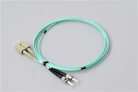
Common connector families include LC, SC, FC, and ST. Patch cords come in single-mode and multimode versions, and in simplex or duplex constructions depending on the application.

Fiber Jumper vs Patch Cord: Is There a Difference?
In practice, "fiber jumper" and "fiber optic patch cord" refer to the same product. Both describe a connectorized cable used for flexible optical patching. The terminology varies by region and vendor preference, but the function is identical. A related but different product is the fiber pigtail, which has a connector on only one end and is typically spliced to trunk cable rather than used for removable connections.
How to Choose the Right Fiber Jumper
Picking the right jumper before you open the bag prevents the most common installation mistakes. There are four decisions to make: connector type, fiber type, cable construction, and length.
Match the Connector Type to the Port
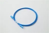
Check the physical interface on both endpoints. If the equipment uses LC ports, use an LC fiber jumper. If the panel side is SC, use an SC patch cord. Do not force a connector into a mismatched adapter - it may seat partially but will create loss and risk damaging the ferrule or the port.
In high-density data center environments, LC dominates due to its small form factor. SC and FC remain common in telecom cabinets and legacy installations. For high-fiber-count trunk connections, MPO/MTP connectors are increasingly standard.
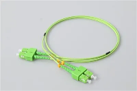
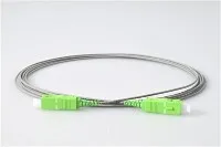
Also pay attention to the connector polish type - PC, UPC, or APC. An APC connector (angled physical contact, usually with a green ferrule boot) must mate with another APC connector. Connecting APC to UPC causes high return loss and poor signal quality. This is one of the most frequently overlooked mismatches in field installations.
Single-Mode vs Multimode: Match the Fiber Type to the Link

The jumper's fiber type must match the system it connects to. A single-mode fiber jumper on a multimode link - or vice versa - creates severe attenuation and unreliable transmission. The core diameter mismatch alone can cause several dB of loss at each connection point.
A quick visual check helps: single-mode patch cords typically use yellow jackets with blue or green boots, while multimode cords are orange (OM1/OM2) or aqua (OM3/OM4). However, always verify the cable marking rather than relying on color alone, especially with non-standard vendors.
| Feature | Single-Mode (OS2) | Multimode (OM3/OM4) |
|---|---|---|
| Core diameter | 9 µm | 50 µm |
| Typical jacket color | Yellow | Aqua |
| Reach | Long-haul, up to tens of km | Short-reach, typically under 300–550 m |
| Common applications | Telecom, campus backbone, FTTH | Data center intra-building links |
| Cost per jumper | Slightly higher (tighter tolerances) | Lower |
Simplex vs Duplex, and Choosing the Right Length
A simplex jumper carries one fiber and is used where only a single optical path is needed - for instance, monitoring taps or certain PON connections. A duplex jumper pairs two fibers for separate transmit and receive paths, which is the standard configuration for most Ethernet and transceiver connections.
Length selection matters more than many installers realize. A jumper that is too short forces the cable into a strained path, risks pulling on the connector, and may violate bend radius limits at the back of the patch panel. A jumper that is far too long creates slack management problems - excess fiber looped tightly behind a rack panel is a common source of hidden macrobend loss. Measure the actual routing path and add a small service margin, but avoid defaulting to "the longest one in the box."
Factory-Terminated vs Field-Polished
For standard patching, factory-terminated jumpers offer more consistent endface geometry and lower insertion loss compared to field-polished assemblies. Field termination has its place - particularly in fast connector or fusion splicing scenarios where custom lengths are needed on-site - but a factory cord is the safer default when a standard length works.
How to Install a Fiber Jumper Step by Step

Step 1: Prepare Before Touching the Cable
Before you pull the jumper out of its bag, confirm both endpoints. Identify the exact port on each side, verify the connector type and polish, and confirm the fiber type matches the link. Prepare your labels in advance - writing them after the patch is connected, while leaning into a crowded rack, is when labeling gets skipped.
If validation is part of the job scope, have your tools staged: a visual fault locator (VFL), a connector inspection microscope, fiber-safe cleaning supplies, and test equipment such as an optical loss test set (OLTS) or optical power meter and source. The Fiber Optic Association (FOA) provides detailed guidance on certification test procedures and recommended tool lists.
Step 2: Inspect and Clean Before Connecting

This is the single most impactful step, and the one most often skipped. Connector contamination - dust, oils, and residue from handling - is widely recognized in the industry as the leading cause of fiber link failures and test failures. Even a new connector straight from a sealed bag can carry particles that cause measurable loss or back-reflection.
The correct routine is: inspect the endface under magnification, clean if any contamination is visible, then inspect again to confirm the surface is clear. Clean both mating surfaces - plugging a dirty connector into a clean adapter contaminates the adapter, and the next connector plugged into that adapter inherits the problem.
Use cleaning tools designed specifically for fiber connectors: dry wipes, click-style cleaners, or lint-free swabs with appropriate solvent for stubborn residue. Do not use compressed air cans intended for electronics - they can deposit propellant residue on the endface. For more detailed cleaning procedures, refer to our fiber connector maintenance and cleaning guide.
Step 3: Route the Jumper Properly
Route the jumper through designated cable management - horizontal trays, vertical channels, or panel guides - rather than draping it across open rack space. Poor routing is where many "unexplained" performance issues originate.
Watch for these specific hazards:
- Cabinet door pinching: A jumper routed across a hinge point can get crushed every time the door closes. This is one of the most common field-damage scenarios in enclosed cabinets.
- Tight bend radius: Every patch cord has a minimum bend radius specified by the manufacturer, typically 10–15 times the cable outer diameter for standard 2.0 mm or 3.0 mm cords. Bending tighter than this limit increases attenuation and can permanently damage the fiber. According to IEC 61753 and related standards, optical performance is tested under specified bend conditions, and exceeding them voids those performance guarantees.
- Excessive pull force: If the jumper does not reach comfortably, the answer is a longer jumper - not pulling harder. Tension on the connector can cause the ferrule to misalign in the adapter or micro-crack the fiber.
- Over-tight bundling: Cable ties cinched tightly around a group of patch cords look organized but can create point-pressure macrobend loss. Use hook-and-loop wraps instead, and leave enough slack for individual cords to move. For more on cable management strategies, see our article on fiber optic jumper management methods.
Step 4: Connect and Label Both Ends
Insert the connector straight into the adapter until it clicks or latches. Do not twist the cable body to seat the connector - rotate only the connector housing if the interface design requires it (as with FC bayonet-style connectors). Once seated, give a gentle tug to confirm it is locked.
Then label both ends immediately. In a live data center row or telecom cabinet, an unlabeled jumper is a liability. Every MAC (move, add, change) operation that touches unlabeled cords risks pulling the wrong connection. A consistent labeling scheme - matching port IDs, circuit references, or cable numbers on both ends - pays for itself the first time someone needs to trace a fiber without a VFL.
Step 5: Test and Verify the Link
Do not assume the link is good because the connector clicked. At minimum, verify continuity with a VFL or visible light source to confirm the fiber path is correct and unbroken. For loss verification, use an OLTS configured for the correct wavelength and fiber type.
OTDR testing provides additional information about the link - splice loss, connector reflections, and distance to faults - but requires trained interpretation and is typically used for trunk cables and installed plant rather than short jumpers. The FOA recommends that OTDR testing be performed by personnel who understand the equipment and can correctly interpret the trace. For short jumpers, an insertion loss test with a power meter is usually the faster and more appropriate verification method.
Common Fiber Jumper Mistakes and How to Avoid Them

After years of field deployment, certain mistakes appear again and again. Here are the ones that cause the most rework:
Wrong jumper selection.
Connector mismatch, wrong polish type (APC into UPC), or wrong fiber type. This usually happens when spares are grabbed from a mixed bin without checking the markings. Label your inventory.
Skipping inspection because the connector "looks clean."
A dust cap is not a seal - it reduces exposure but does not guarantee a clean endface. Particles invisible to the naked eye are enough to cause measurable insertion loss. Always inspect at the microscope level.
Routing shortcuts.
Running a jumper diagonally across a rack opening or under a raised floor tile "just for now" creates a tripping hazard, a crush risk, and a path that nobody documents. Temporary routes become permanent installations surprisingly fast.
No labels.
In a panel with 48 or 96 LC ports, finding an unlabeled jumper by trial-and-error means disrupting live services. Labeling takes seconds; the outage it prevents can take hours to resolve.
Reusing visibly damaged cords.
If the connector ferrule shows scratches under inspection, or the cable jacket has stress marks, kinks, or crushed sections, replace the jumper. The cost of a new patch cord is trivial compared to the cost of intermittent failures that are difficult to reproduce and diagnose.
Fiber Jumper Troubleshooting
When a link fails to come up after patching - or shows higher loss than expected - work through these checks before escalating to advanced testing. For a broader look at fiber network diagnostics, see our fiber optic troubleshooting guide.
Verify port identity.
Confirm both ends are plugged into the correct ports. In high-density panels, it is easy to be off by one position, especially with LC duplex connectors that sit close together.
Check the jumper specification.
Make sure the connector type, polish, and fiber mode match what the link requires. A single-mode jumper in a multimode link (or vice versa) will not work reliably, even if the connectors physically fit.
Inspect and clean.
Remove the connector, inspect the endface, clean it, inspect again, and reconnect. If the adapter itself may be contaminated, clean the adapter bore as well.
Check the routing.
Look for sharp bends, pinch points, or tension along the cable path. A jumper that is pulled taut between two racks may technically reach, but the strain can cause enough microbend loss to degrade a marginal link.
Swap the jumper.
If the above checks do not resolve the issue, replace the jumper with a known-good spare. This is faster than prolonged diagnosis on a potentially defective cord, and it immediately confirms or eliminates the jumper as the cause.
Safety reminder: Never look directly into an energized fiber connector or adapter port. Infrared laser light used in telecom systems is invisible but can cause eye injury. If you need to inspect a connector on a live link, use an inspection microscope designed for in-service use, or ensure the far-end transmitter is disabled first.
Where Fiber Jumpers Are Used: Application Scenarios

The same jumper product serves different roles depending on the environment:
Data center patching.
In high-density data center environments, LC and MPO jumpers connect switches to structured cabling systems. Density drives the need for small-form-factor connectors, careful cable management, and fast MAC operations. Uniboot LC patch cords reduce cable volume by combining both fibers into a single jacket.
Telecom central office and ODF.
In telecom environments, jumpers connect active equipment to optical distribution frames. SC and FC connectors remain common here, and jumpers may stay in place for years - making initial quality and labeling especially important.
FTTH and access networks.
In fiber-to-the-home deployments, patch cords connect splitters to distribution panels and terminal boxes to subscriber equipment. SC/APC is the dominant connector type in most PON architectures due to its low return loss.
Testing and lab environments.
Reference-grade jumpers with known loss values are used as test leads in lab setups and certification workflows. These are typically handled more carefully and stored with protective caps after every use.
Frequently Asked Questions
Can single-mode and multimode fiber jumpers be mixed on the same link?
No. Mixing fiber types on a single optical path causes a core diameter mismatch (9 µm vs 50 µm) that introduces substantial loss. The jumper must match the fiber type of the system it connects to. For a detailed comparison, see our guide on single-mode vs multimode fiber.
How often should fiber connectors be cleaned?
There is no universal cleaning schedule. The reliable practice is to inspect before every connection or test, and clean whenever contamination is visible. In environments with high dust exposure or frequent patching activity, connectors may need cleaning more often. The principle is inspect-driven, not calendar-driven.
What happens if a fiber jumper is bent too tightly?
Exceeding the minimum bend radius causes increased attenuation through macrobending - light escapes the core at the bend point. In severe cases, the fiber itself can crack. The specific limit depends on the patch cord design and is stated on the manufacturer's datasheet, but a general guideline is to never bend tighter than 10 times the cable outer diameter under load.
How long should a fiber jumper be?
Measure the actual routing path between the two endpoints, including vertical runs, horizontal trays, and any service loops, then add a small margin (typically 0.3–0.5 m). Avoid the habit of always ordering the same length - a 3 m jumper for a 1 m path creates unnecessary slack that must be managed, while a 1 m jumper for a 1.5 m path creates strain and bend radius violations.
Can I mix APC and UPC connectors?
No. APC (angled physical contact) and UPC (ultra physical contact) connectors have different endface geometries - 8° angle vs flat - and are physically incompatible when mated. Connecting APC to UPC results in high insertion loss, high return loss, and potential damage to both ferrule surfaces. Always mate APC with APC and UPC with UPC. Learn more in our guide to PC, UPC, and APC polish types.
What is the difference between a fiber pigtail and a patch cord?
A fiber pigtail has a connector on one end and a bare fiber on the other, designed to be fusion-spliced to trunk cable. A patch cord has connectors on both ends and is used for removable connections. They serve different roles in the cabling architecture: pigtails are semi-permanent splice-to-connector transitions, while patch cords are the flexible, field-changeable links.
References
- Fiber Optic Association (FOA) - Fiber Optic Testing and Certification
- IEC 61753 - Fibre optic interconnecting devices and passive components - Performance standard (available via IEC)
- TIA-568 - Telecommunications Infrastructure Standard for Customer Premises (available via TIA)