Start with the optic. If the link uses 40G SR4, 100G SR4, or 100G PSM4, MPO patch cords are part of the design. If it uses LR4, DR, FR, CWDM4, or another duplex-LC optic, an MPO patch cord is the wrong path. After that, the selection becomes much simpler: choose the right fiber type, fiber count, cable format, polarity, connector gender, loss grade, and length.
A lot of confusion around MPO comes from mixing several decisions together. People compare OM3 and OM4 before confirming the interface. They talk about Type A and Type B before checking whether the link even stays MPO from end to end. They look at product pages before looking at the transceiver. That is why this guide follows a fixed order. Each step removes wrong options first, then narrows the right one.
| Link Type | Typical Connector Style | Usual Fiber Type | Patch Cord Direction |
|---|---|---|---|
| 40G SR4 | MPO | Multimode | Usually MPO patch cord |
| 100G SR4 | MPO | Multimode | Usually MPO patch cord |
| 100G PSM4 | MPO | Single-mode | Usually MPO patch cord |
| 100G LR4 / DR / FR / CWDM4 | Duplex LC | Single-mode | Not an MPO patch cord job |
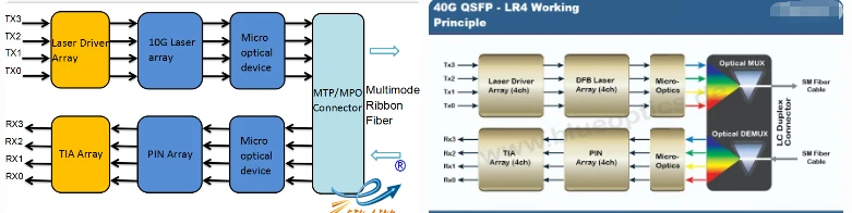
Step 1: Check the optic before checking the cable
The optic decides the patch cord, not the other way around. That sounds basic, but it is where many wrong orders start.
For 40G and 100G links, the first split is easy. SR4 and PSM4 lead toward MPO. LR4, DR, FR, and CWDM4 do not. Once that is clear, a large part of the cable catalog stops mattering. There is no need to compare MPO patch cords for a link built around duplex LC optics.
This also prevents the article from turning into a general fiber guide. The topic here is not every cable used in high-speed networks. It is the part of 40G/100G cabling where MPO patch cords actually belong. For a wider background on where MPO assemblies fit in structured fiber systems, see where MPO fiber jumpers are mainly used.
Step 2: Choose multimode or single-mode
After confirming that the link really uses MPO, the next question is fiber type.
For 40G SR4 and 100G SR4, the normal choice is multimode fiber. In most projects, that means OM3 or OM4. OM3 still works for shorter runs and tighter budgets. OM4 is usually the safer option for new builds because it gives more reach margin and a bit more breathing room in the loss budget. In plain terms, OM4 leaves less room for regret later.
100G PSM4 changes the situation. It still uses MPO connectivity, but the media is single-mode fiber, not multimode. That is why it is dangerous to stop at "MPO means multimode." It often does, but not always.
OM5 exists, but it is rarely the first filter in a normal 40G/100G patching job. In real deployments, the more common failures are much simpler: wrong interface, wrong polarity, wrong gender, or wrong breakout choice. Those mistakes are more common than choosing OM3 when OM5 was theoretically possible.
For a deeper comparison of multimode grades, see OM1, OM2, OM3, OM4, and OM5.

Step 3: In many SR4 links, 12-fiber is still the default
This is one of the most useful practical questions in the whole topic: how many fibers are usually involved?
For many 40G SR4 and 100G SR4 links, the market still revolves around MPO-12 style patching. That is why 12-fiber patch cords keep showing up in real projects even when the signaling model itself is based on eight active fibers. The physical connector format and the live traffic lanes are related, but they are not the same thing.
That matters because many articles stay at the theory level and never connect it back to an actual product decision. In practice, if the job is a short-reach multimode SR4 link between cabinets, patching zones, or rack rows, a 12-core OM4 MTP/MPO patch cord is often the most natural starting point.
This does not mean every 40G/100G MPO link uses the exact same fiber count. It means that when no special topology has been introduced yet, MPO-12 is still where many valid designs begin.
Step 4: Know the difference between a patch cord, a trunk, and a breakout cable
This is where many pages become muddy. They use MPO cable, MPO trunk, MPO jumper, and breakout cable almost interchangeably. That makes the reader more confused, not less.
An MPO patch cord is usually the shorter connection piece used between ports, panels, cassettes, or nearby connection points. A trunk cable is the longer pre-terminated backbone segment used to connect larger parts of the cabling system. A breakout cable takes a multi-fiber MPO connection and fans it out into duplex legs such as LC. These are not three names for the same thing. They solve three different problems.
That distinction matters because some 40G/100G links stay MPO from one end to the other, while others do not. If the path is native MPO to native MPO, a straight jumper is usually the clean answer. If the design needs to split a parallel link into duplex paths, a breakout cable is the right tool.
For breakout scenarios, an 8-core MTP-to-LC breakout patch cord is a much better reference point than a standard MPO jumper page.
| Cable Type | Main Job | Typical Use |
|---|---|---|
| MPO Patch Cord | Short equipment or panel connection | MPO port to MPO port, cassette to switch, panel to panel |
| MPO Trunk Cable | Backbone or longer pre-terminated run | Structured cabling between zones or cabinets |
| MPO Breakout Cable | Fan-out from multi-fiber to duplex legs | Parallel link split into LC connections |

Step 5: Get polarity right before talking about price
A wrong polarity setup wastes far more time than a slightly cheaper cable ever saves.
Type A, Type B, and Type C are different polarity methods, not casual variations. The correct choice depends on the whole channel: transceivers, trunks, cassettes, panels, and the way transmit lanes map to receive lanes.
Type B is common in parallel-optics environments, so it often gets treated like a shortcut answer. That shortcut causes problems. If the existing channel was built around another method, dropping in a Type B patch cord does not simplify anything. It just creates a mismatch that will surface later as a dead link or a confusing patch history.
The safe rule is simple: match polarity to the full path, not to habit. If the channel design is still unclear, stop there and confirm it before ordering anything.

Step 6: Confirm connector gender
Polarity alone does not finish the job. Connector gender matters too.
In MPO systems, the transceiver-side interface is typically male. A patch cord that plugs directly into that port is usually female, or unpinned. This is easy to overlook because many product listings focus on fiber type and length first, while the mating style gets pushed into the small print.
This is also why wrong orders can look perfectly reasonable until the cable arrives. Everything seems compatible until the mating side is wrong. Then the entire job stalls because one basic detail was assumed instead of checked.
The easiest way to avoid that problem is to verify polarity and gender at the same time. If one is still unclear, the spec is still incomplete.

Step 7: Choose loss grade, jacket, and length for the real route
Once the interface, fiber type, fiber count, format, polarity, and gender are correct, the last set of decisions becomes much easier.
Low-loss assemblies matter most when the channel already has several mating points or limited optical margin. In a short and simple patch path, standard-grade assemblies may be enough. In a denser path with more connectors and less tolerance for extra loss, low-loss options make much more sense.
Jacket choice should follow the environment. In clean indoor data center spaces, standard indoor-rated assemblies are usually the right fit. There is no need to overcomplicate a protected route with the wrong construction. On the other hand, if the installation path has stricter rating requirements or more physical stress, jacket selection deserves closer attention.
Length should be chosen for the real route, not for the quote sheet. Too short creates strain. Too long creates loops, tighter bends, and messy routing. The best patch cord length is the one that fits the path cleanly and leaves sensible service slack without creating cable clutter behind the panel.
Step 8: Do not ignore inspection and verification
A technically correct patch cord can still behave like a bad one if the end face is dirty or the installed link is never checked.
That is why inspection, cleaning, and basic verification belong in this topic. This does not need to turn into a long testing manual. The point is simpler than that. After choosing the right MPO patch cord, the link still needs clean connectors, correct polarity, and acceptable insertion loss.
For field issues after installation, see common issues in fiber optic networks. For a straightforward patch-cord check workflow, see how to test a fiber optic patch cord.

MTP vs MPO: where it matters and where it does not
MPO is the generic connector format. MTP is a higher-performance MPO-style connector with tighter tolerances and performance-oriented refinements.
That difference matters when the job needs tighter insertion-loss control, better repeatability, or more stable performance over repeated mating cycles. It does not change the first decision in the process. The first decision is still whether the link uses MPO at all.
So the order stays the same: first confirm the optic and interface, then decide whether a standard MPO assembly is enough or whether an MTP-grade solution makes more sense.

Common mistakes that cause wrong MPO patch cord orders
- Starting from the cable page instead of the transceiver spec.
- Assuming every 100G link uses MPO.
- Mixing up patch cords, trunks, and breakout cables.
- Choosing Type B because it is "common" without checking the full channel.
- Ignoring connector gender until the order has already shipped.
- Picking length by guess instead of the real routing path.
- Treating inspection and cleaning as optional.
Quick selection checklist
- Check the optic family first.
- Confirm whether the port is MPO or duplex LC.
- Choose multimode or single-mode based on the optic.
- For many SR4 links, start from MPO-12.
- Decide whether the link stays MPO or needs breakout.
- Match polarity to the full channel.
- Confirm connector gender on both mating sides.
- Choose loss grade, jacket, and length for the real route.
- Inspect and verify after installation.
FAQ
Q: Do All 100G Links Use MPO Patch Cords?
A: No. 100G SR4 and 100G PSM4 are common MPO cases. Many other 100G optics use duplex LC instead.
Q: What Is Usually Used For A 100G SR4 Link?
A: In many short-reach data center links, the starting point is a 12-fiber multimode MPO/MTP patch cord, often OM4.
Q: Is OM4 Better Than OM3 For Short 40G/100G Links?
A: For many new builds, yes. OM4 gives more headroom and is usually the safer long-term choice. OM3 still works in shorter and more cost-sensitive links.
Q: Do All 40G/100G MPO Links Use Type B?
A: No. Type B is common, but it is not universal. The correct polarity depends on the full channel design.
Q: When Should A Breakout Cable Be Used?
A: Use breakout when the link needs to split into duplex legs or connect into a fan-out path. Use a straight MPO jumper when the link stays MPO end to end.
Q: What Is The Practical Difference Between MPO And MTP?
A: MPO is the generic format. MTP is a higher-performance MPO-style connector. The selection order does not change: first confirm the interface, then choose the connector grade.