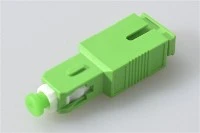
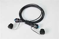
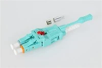
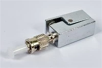
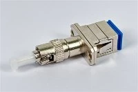
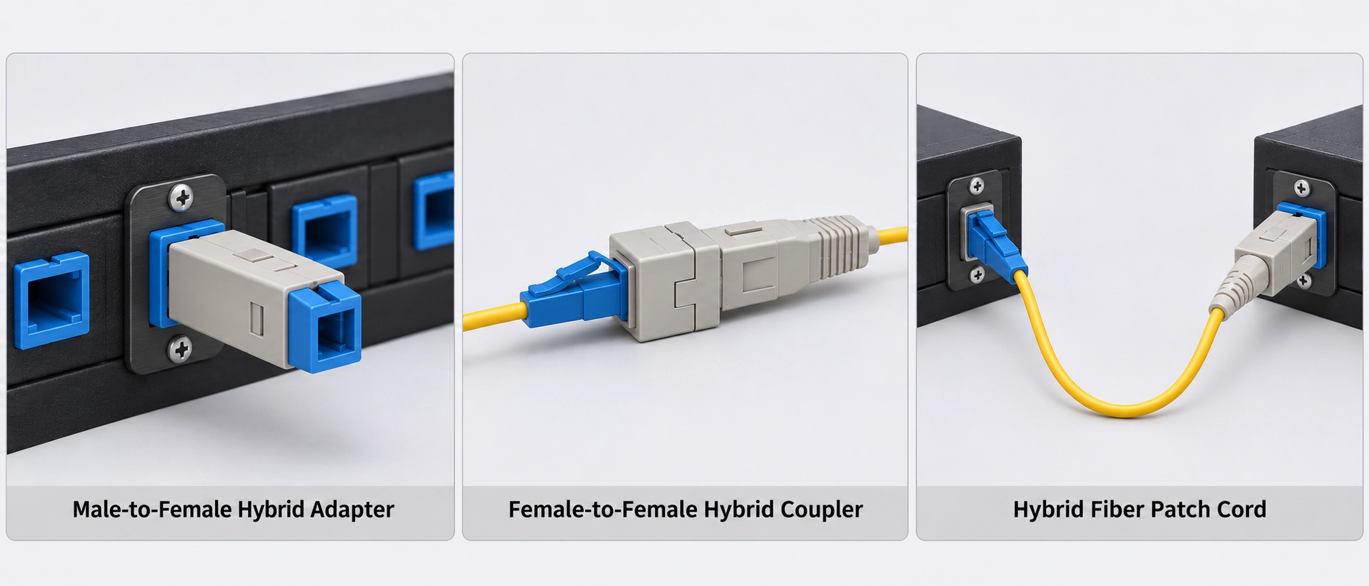
A male-to-female hybrid fiber optic adapter is a candidate when an existing socket must accept a cable plug with a different connector format. Choose it by recording the fixed port and cable connector separately, then checking the polish, fiber type and installed clearance at both ends. A label such as "SC to ST" leaves too much unspecified for a purchase order.
For a legacy cabinet retrofit, the decision is practical: can the proposed assembly mate correctly, remain accessible with the cabinet closed, and meet the agreed optical acceptance requirements? The following checks help an installer or system integrator decide before ordering a sample.
When a Plug-In Hybrid Adapter Fits a Legacy Port
Start with the two items already in place. "Male" means a connector plug; "female" means the socket that receives it. This distinction identifies the mechanical arrangement, not the direction in which light travels.
| Existing connection | Candidate arrangement | Condition to confirm |
|---|---|---|
| One fixed socket and one cable plug of a different format | A male-to-female hybrid adapter | Its plug fits the fixed socket; its socket accepts the cable plug. Check polish and fiber compatibility at both sides. |
| Two existing cable plugs of different formats | A suitable female-to-female hybrid coupler | Each socket must match its corresponding plug. Confirm the complete optical arrangement rather than choosing by connector names alone. |
| Two fixed sockets, or a connection needing flexible routing | A hybrid patch cord with the required plugs | Confirm the two terminations, fiber specification, length and routing space. |
Use this table to choose an architecture before choosing a part. If a rigid adapter would obstruct access, changing its connector combination will not solve the installation problem.
Match the Two Mating Interfaces
Write down the connector that enters each socket and the optical interface it meets. On a conventional through-coupled patch panel, the front socket guides the adapter plug toward the connector installed at the rear. In that arrangement, record the rear connector's polish as well as the front socket format. An active-device or test-instrument receptacle may have a different internal arrangement; use the manufacturer's port instructions.
For checks across the rest of the installed link, use the port-first fiber connector compatibility guide. The two examples below focus on the proposed adapter's plug, socket and external mating interfaces.
These are conditional selection examples based on Evolux's public product descriptions. They do not establish compatibility with a particular equipment model.
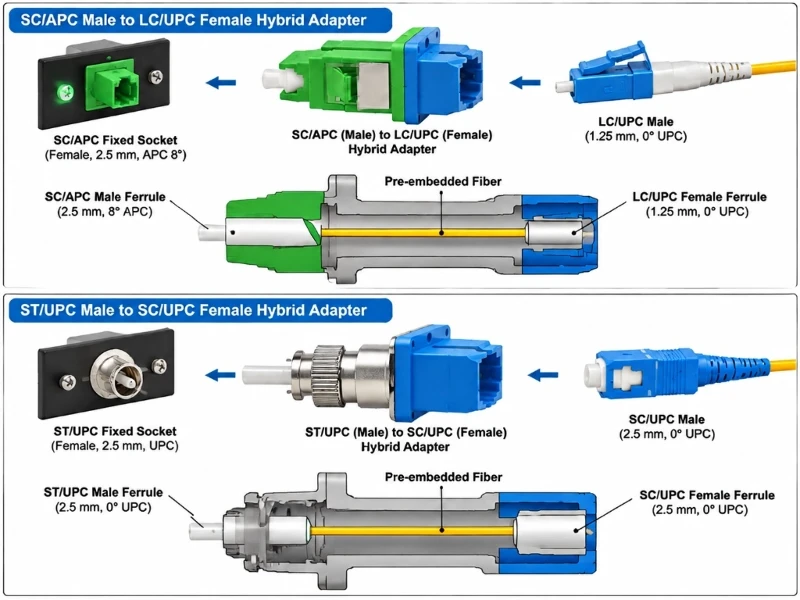
SC/APC Plug to LC/UPC Socket
Evolux lists an SC/APC male to LC/UPC female single-mode hybrid adapter with a publicly described pre-embedded fiber structure. Use the listed interfaces to assess the following arrangement; obtain a part-specific drawing and verify a sample before approving the configuration.
| Location | Existing interface | Required adapter interface |
|---|---|---|
| Equipment or panel front | SC/APC socket into which the adapter plug will be inserted | SC/APC male plug; for a through-coupled panel, it must meet an SC/APC connector at the rear |
| Cable side | Compatible single-mode LC/UPC male connector | LC/UPC female socket |
At the external contact interfaces, the APC end must meet a compatible APC interface and the UPC end must meet a compatible UPC interface. These are two separate external mating interfaces. Confirm the internal transition structure from the manufacturer's part-specific drawing; do not interpret the product name as permission to mate an APC ferrule directly against a UPC ferrule. Fluke warns that directly mating those two finishes can cause poor performance and endface damage. (Fluke Networks)
This example does not cover an LC socket on the equipment and an SC plug on the cable: that requires the opposite plug/socket arrangement. Nor does changing connector format establish that a multimode cable is suitable for a single-mode link.
ST/UPC Plug to SC/UPC Socket
For a fixed ST/UPC socket and an existing SC/UPC cable plug, the candidate arrangement is an ST/UPC male plug with an SC/UPC female socket. That is the arrangement named on the Evolux SC/UPC female to ST/UPC male hybrid adapter product page. Reversing the order of the names does not reverse the physical part.
| Location | Existing interface | Required adapter interface |
|---|---|---|
| Equipment or panel side | ST/UPC socket with a compatible mating interface | ST/UPC male plug |
| Cable side | SC/UPC male connector | SC/UPC female socket |
Select the exact fiber version before ordering. A listing that mentions single-mode and multimode options does not mean one supplied assembly is suitable for all fiber types. Request the configuration number, fiber specification, connector finishes and simplex or duplex arrangement together; the public listing alone does not establish which version will be supplied.
Connector appearance is insufficient evidence of compatibility. FOA identifies SC and ST as using nominal 2.5 mm ferrules, while LC uses a smaller 1.25 mm ferrule. Shared ferrule size does not establish matching polish or fiber characteristics; different sizes require an appropriate hybrid structure. (FOA)
Check Clearance Before Choosing Direct Mounting
Treat the adapter, cable plug and boot as one installed assembly. A bare adapter may fit while the connected cable prevents the enclosure door from closing or makes the adjacent port difficult to release.
For the sample fit check, use the panel face as a stated measurement datum and record:
- Available depth to the closed door or nearest obstruction.
- Installed projection of the adapter with the cable connector fully seated.
- Space needed for the boot and cable to turn without violating the cable manufacturer's minimum bend radius.
- Access to the SC push-pull body, LC latch or ST bayonet mechanism, as applicable.
- Clearance to remove the assembly and service neighboring ports.
- For a separately panel-mounted adapter, the cutout dimensions, panel thickness, flange orientation, clip/screw/snap-in retention, fastener locations and port spacing. Check these against the part-specific drawing; for a plug-in unit, confirm how the existing port retains the assembly.
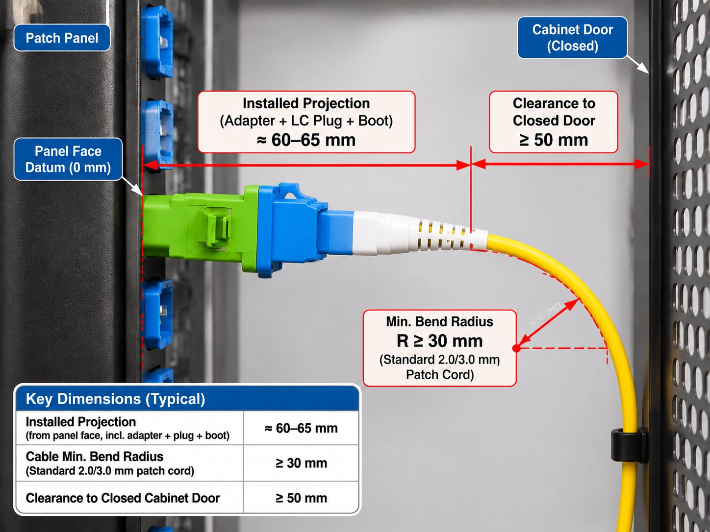
Close and reopen the cabinet during the check. Confirm that the door does not press against the plug or cable and that the connection can be released without pulling on the fiber cable. For enclosure and routing decisions beyond the individual port, use the patch panel and ODF selection guide.
When a Hybrid Patch Cord Is the Better Fit
Choose a flexible connection when the rigid assembly fails the clearance or service-access check and a correctly routed cord can meet the requirements. A hybrid patch cord places the required connector at each end while allowing the route between them to change.
The cord still needs suitable fiber, matching polish at each mating interface, sufficient routing space and an agreed optical budget. It is not automatically preferable merely because it bends. Specify the two plugs, fiber type and required length, then check the proposed cord against the same mating-interface and optical acceptance requirements.
If both existing cables already end in plugs, reconsider whether a female-to-female coupler is the appropriate arrangement. Do not add a male-to-female adapter without first mapping the resulting interfaces.
Verify Optical Performance Before Accepting the Adapter
Mechanical fit and a clean-looking endface do not establish optical performance. IEC 61300-3-35:2022 covers visual inspection of connector and fiber-stub transceiver endfaces; its public scope explicitly distinguishes inspection from attenuation and return-loss measurements. (IEC)
Inspect the accessible mating endfaces using the appropriate probe tips, clean them with a suitable connector-cleaning method, and inspect again before mating. Apply the procedure to the reference leads as well as the sample. FOA discusses contamination of connectors, adapters and instrument ports and recommends inspection after cleaning. (FOA)
Define the Reference Planes and Test Conditions
Agree what the insertion-loss result includes before comparing a sample with a requirement. Is the reported value for a specified interface, the complete adapter with its external mating connections, or a longer installed path? These are different measurement boundaries.
FOA explains that reference-cable arrangements affect which connection losses are included in the result. For a hybrid assembly, the test plan must identify compatible reference connectors and show the reference and measurement configurations. Follow the chosen method and the instrument instructions rather than treating any displayed dB value as a directly comparable adapter specification. (FOA)
For insertion-loss acceptance, use an optical light source and power meter, or a loss-test set, with compatible reference leads and a documented reference procedure. Show the connections from the source through the launch lead, the adapter under test and the receive lead to the meter, and identify which mating connections the reference procedure includes. Do not substitute an unresolved OTDR event for this measurement.
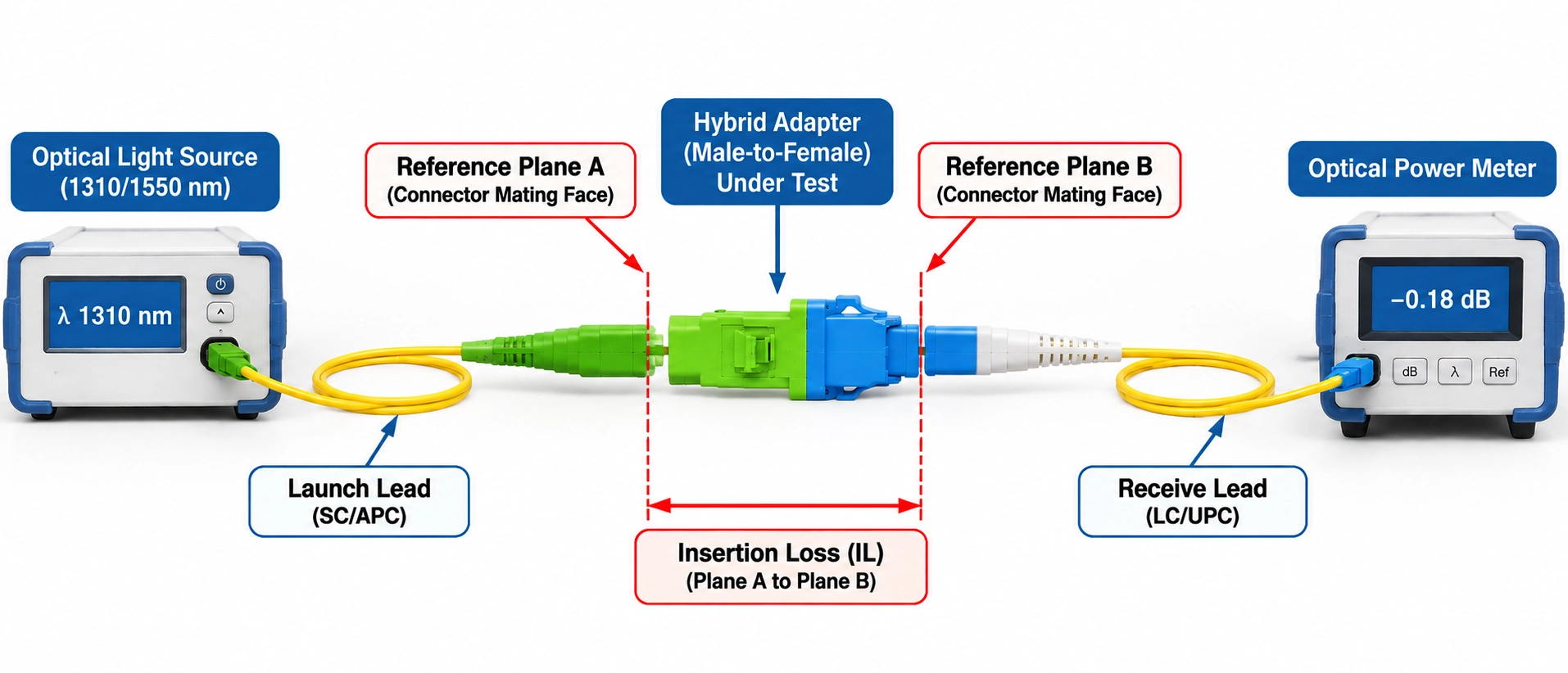
Use the following record as a proposed acceptance worksheet. Set the limits with the responsible engineer before testing; no universal pass value is implied.
| Record field | What to document |
|---|---|
| Sample identity | Part number, drawing revision, sample identifier and test date |
| Optical configuration | Fiber type, both connector formats and finishes, test direction and wavelength |
| Instruments and leads | Instrument models, relevant calibration status, port interfaces and reference-lead identities |
| Measurement boundary | Diagram of the reference setup and test setup, showing included mating connections |
| Launch conditions | Applicable source and modal launch requirements for the selected fiber and method |
| Inspection and fit | Inspection procedure, cleaning/reinspection outcome and cabinet fit observations |
| Insertion loss | Agreed maximum, measured result, units and method |
| Reflection requirement | Event reflectance, component return loss or link ORL, with measurement boundary, method, limit and result |
| Disposition | Acceptance decision under the agreed plan, reviewer and any unresolved deviation |
Keep reflection terminology explicit. Event reflectance is normally expressed as a negative dB value: more negative means less reflected power. Return loss expresses the inverse ratio as a positive dB value: a larger value means less reflected power. An OTDR's link ORL can include reflections and distributed backscatter across a defined length, so it must not be substituted for a single-interface result. (FOA)
An OTDR's pulse width and recovery after a reflection limit its ability to separate nearby events. FOA describes these resolution and dead-zone effects in its OTDR testing reference. For a short adapter assembly, check the instrument's specifications and selected settings before treating its interfaces as separately resolved events. A launch lead helps address the near-end dead zone; it does not establish that the assembly's closely spaced interfaces can be resolved individually.
Use a measurement method suited to the required quantity, and identify whether the result describes an event, a component assembly or an entire link. For a test-instrument port, follow the model-specific mating instructions before inserting a hybrid adapter.
Send Evolux the Two Interfaces for a Quote
For an Evolux hybrid fiber adapter inquiry, send a description that can be checked against a specific part rather than only "SC to LC" or "SC to ST." Include:
- Fixed-port manufacturer, equipment model, port photograph and connector/polish identification.
- Existing cable part number, fiber specification, connector type and polish.
- Required adapter plug and socket, with the mating object identified at each side.
- Cabinet photographs, available depth, routing constraints and service-access requirements.
- Exact fiber mode/specification and required simplex or duplex arrangement, including channel identification where applicable.
- Requested adapter part number or configuration reference, if known; otherwise ask Evolux to identify the proposed configuration in the quotation.
- Housing and mounting requirements. Where relevant, include flange details, panel cutout and port spacing.
- Sample quantity and expected order quantity.
- Proposed optical test boundary, method, wavelengths and acceptance limits.
Ask for a part-specific drawing and confirmation of the supplied configuration before approving a sample. Evaluate that sample using the same interface record and acceptance plan that will apply to the order.
Browse Evolux Fiber Optic Adapters to locate the listed interface combinations.
Send Evolux your port details for a compatibility review and quotation. Send port photographs and drawings to sales@evoluxfiber.com, and ask for the proposed part/configuration, its drawing and the test conditions to be identified in the response.