Fiber pigtail connector compatibility is not determined by a matching connector name or by whether two parts physically fit. A working link requires the connector interface, end-face polish, fiber mode, optic and wavelength, and simplex/duplex polarity to agree across the entire connection path.
An LC pigtail may enter an LC receptacle and still be wrong for the module. An SC-to-LC adapter may complete the mechanical path while leaving a single-mode/multimode, BiDi wavelength, or polarity mismatch unresolved. Before approving a BOM, record the equipment manufacturer and exact module, the port's connector and polish, the installed fiber, the optic or wavelength pair, and the panel/adapter path.
Our working rule is simple: do not approve a fiber pigtail BOM from the connector label alone. Start with the equipment port and work backward. If you send us the exact equipment/module and the installed path, we can identify a compatible pigtail-and-adapter route and flag the fields that still require site verification.
Use Five Gates Before You Approve the BOM
A reliable fiber pigtail connector compatibility check should move through five gates in sequence:
Connector interface → polish → fiber mode → optic/wavelength → simplex/duplex and polarity
If Gate 1 fails, the parts need a deliberate interface conversion. If Gate 2 fails, the housings may mate while the end faces remain incompatible. If Gate 3 or Gate 4 fails, changing a passive adapter cannot make the optical system interoperable. If Gate 5 fails, every individual part may be correct while the completed link remains down.
For background on pigtails, patch cords, and termination architecture, see our fiber optic pigtail knowledge hub. This article stays with one question: whether a pigtail will mate with a specified adapter and equipment port and support the intended optical link.
The five gates separate three questions that should never be collapsed into one:
- Mechanical compatibility: can the interfaces mate directly or through a specified conversion component?
- Optical compatibility: do polish, fiber type, wavelength, and loss/reflectance requirements align?
- System interoperability: do the active optics, architecture, and polarity form a working link?
Gate 1: Match the Physical Connector Interface
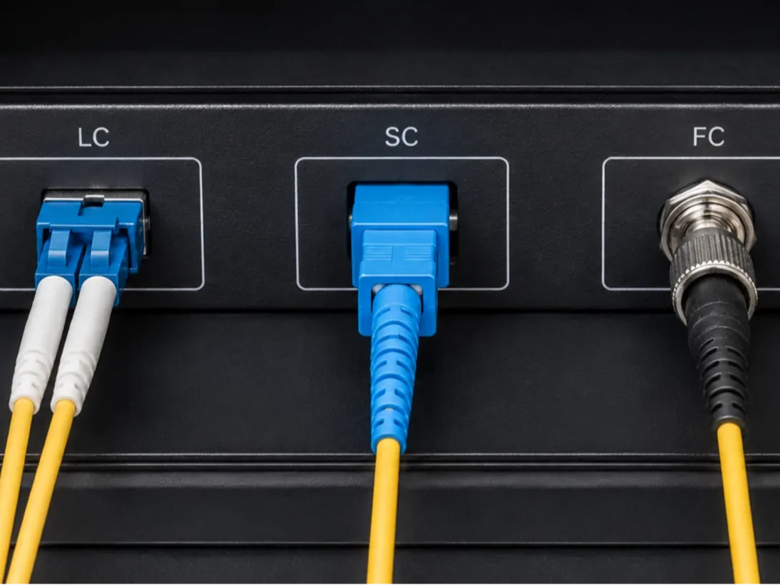
Start with the interface presented by the equipment, patch panel, or adapter. LC, SC, FC, and ST bodies are not directly interchangeable: SC uses a push-pull body, FC uses a threaded coupling, ST uses a bayonet mechanism, and LC uses a small-form-factor latch.
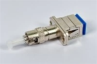
The Fiber Optic Association notes that ST, SC, and FC use 2.5 mm ferrules, while LC uses a 1.25 mm ferrule. Appropriate hybrid adapters can cross-mate some 2.5 mm ferrule families, but shared ferrule diameter does not make the connector bodies directly interchangeable. (FOA connector identifier)
| Connector | Typical ferrule | Coupling style | Direct same-family route | Typical conversion route |
|---|---|---|---|---|
| LC | 1.25 mm | Latch / push-pull | LC to LC | LC to SC is common; verify both polish interfaces |
| SC | 2.5 mm | Push-pull | SC to SC | SC to FC or SC to ST through a specified hybrid component |
| FC | 2.5 mm | Threaded and keyed | FC to FC | FC to SC or FC to ST; verify keying where applicable |
| ST | 2.5 mm | Bayonet | ST to ST | ST to SC or ST to FC |
| E2000 | 2.5 mm-class interface | Push-pull with shutter | E2000 to E2000 | Treat as a dedicated interface unless the conversion is explicitly specified |
A useful fiber pigtail connector compatibility chart must identify both mating interfaces and the location of the conversion: adapter, hybrid patch cord, or permanent splice, rather than merely state "LC compatible" or "SC compatible."
IEC 61754-20 defines LC-family interface dimensions, while ANSI/TIA-604-10-D addresses Type LC intermateability. These standards support mechanical intermateability across compliant products; they do not guarantee that polish, fiber, optics, wavelength, or polarity are correct. (IEC 61754-20; TIA-604-10-D announcement)
Gate 2: Match UPC or APC at Every Mating Point
A matching housing can still fail at the end face. For every physical-contact pair, identify the polish and geometry on both sides:
equipment receptacle ↔ patch cord ↔ adapter ↔ pigtail ↔ splice ↔ trunk fiber
APC commonly uses an 8° angled end face to direct reflected light away from the optical path. PC/UPC interfaces use a different geometry. Directly mating APC to PC/UPC can create abnormal loss and reflectance and may damage the contact surfaces; matching LC or SC housings do not make that pair acceptable. (FOA connector and polish names)
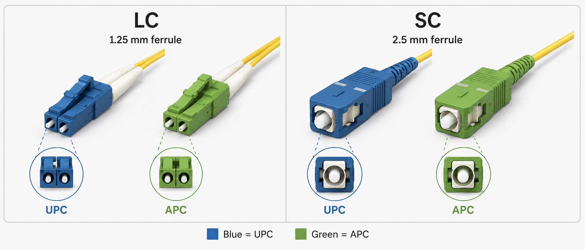
For LC UPC vs LC APC compatibility, check the polish required by the exact port or removable adapter, not only the color. Green and blue are useful identification aids, but replacement housings, field changes, and vendor conventions make color an unreliable purchase specification.
The equipment datasheet wins over the connector color. The boundary is important: a chassis port label may describe the cage, the installed transceiver may define the optical receptacle, and a removable instrument adapter may define the final mating geometry. Record the specification at the surface the connector actually touches.
A hybrid cable may legitimately use different end specifications when each end mates with its own correct interface. What is unacceptable is a direct APC-to-UPC contact pair hidden inside a chain whose outer connector families appear correct.
Write the polish into the BOM: LC/UPC, SC/APC, or FC/APC, instead of ordering "LC," "SC," or "FC." For the geometry and reflection trade-offs, see our LC UPC vs LC APC compatibility
Gate 3: Match Fiber Mode to the Optic
At 850 nm or 1310 nm, the passive adapter performs the same limited job: it aligns connector ferrules. It cannot convert multimode fiber to single-mode fiber or make the wrong transceiver interoperable.
In a data-center multimode route, an LC adapter may accept the pigtail while the installed fiber or optic remains wrong for the intended OM-class plant. In a single-mode access route, an SC-to-LC conversion may be mechanically correct while the transceivers use incompatible wavelengths. A common field signal is that every connector seats normally, yet the link does not establish or falls outside the expected optical budget; at that point, verify the optic and installed fiber before changing another adapter.
Record single mode fiber pigtail connector compatibility as a complete specification:
connector + polish + fiber designation + target optic/wavelength
"LC multimode" is also incomplete when the design depends on OM3 versus OM4, a defined transceiver family, launch conditions, or an existing cable plant.
Use an adapter to solve an interface problem. Never use an adapter as evidence that the optical system is compatible.
Gate 4: Match Architecture, TX/RX, and Wavelengths
In a simplex BiDi deployment, connector selection reaches into the active architecture. One fiber carries different wavelengths in opposite directions, so the two transceivers must be a complementary pair. In a conventional duplex link, separate fibers carry TX and RX; the connector may be correct while reversed A/B polarity leaves TX facing TX.
- Duplex Ethernet: verify interface, fiber mode, wavelength, and A/B polarity so each transmitter reaches the opposite receiver.
- Simplex BiDi: verify the specified single-mode fiber and the complementary TX/RX wavelength pair at the two endpoints.
- PON or FTTH: verify the OLT/ONT interface, splitter architecture, wavelength plan, optical budget, and polish; do not import assumptions from ordinary duplex Ethernet.
An adapter changes the passive mating path, not the wavelengths generated or received by the optics. When a mechanically complete BiDi path stays down, compare both module part numbers and their TX/RX wavelengths before replacing the passive conversion.
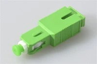
A connector photograph can help identify the housing and color. It cannot establish the optic, wavelength plan, or polarity, so it is supporting evidence rather than a complete BOM input.
Gate 5: Verify Simplex/Duplex Polarity and the Complete Path
The final gate checks the assembled path rather than a single component. Trace the connection from equipment TX through the patching and permanent cabling to the remote RX, then trace the return path. For duplex LC, include cassette or panel polarity. For simplex, verify that the installed architecture really is designed for one fiber.
This gate catches a common purchasing failure: every line item has the right connector, polish, and fiber, but the complete path maps transmit to transmit or uses two identical BiDi modules instead of a complementary pair. The correction belongs in the polarity map or optic pairing, not in another adapter.
Equipment-Port Compatibility Matrix
For procurement, fiber pigtail connector compatibility is easier to approve from a port-first matrix than from a connector catalog because the matrix begins with installed equipment. The entries below are common patterns, not universal rules; verify the exact model datasheet.
| Equipment scenario | Common interface pattern | Fields that decide compatibility | Practical pigtail route |
|---|---|---|---|
| Ethernet SFP/SFP+ duplex optic | Often duplex LC, commonly PC/UPC; SM or MM depends on the module | Exact module SKU, connector/polish, wavelength, fiber mode, polarity | Match the permanent pigtail to the panel; patch to the optic with the specified interface |
| Higher-speed pluggable optic | May be duplex LC, MPO, or another model-specific interface | Exact module SKU and lane architecture; never infer from "QSFP" alone | Design from the module datasheet and breakout architecture |
| FTTH/PON termination | Frequently SC/APC on single-mode access networks | OLT/ONT interface, splitter path, wavelength plan, optical budget | Use SC/APC OS2 only where the actual panel and equipment path require it |
| ODF or distribution panel | LC, SC, FC, ST, or another installed interface | Adapter interface, polish, trunk fiber, splice tray, maintenance plan | Match the permanent pigtail to the panel and upstream cable |
| Optical test equipment | Often FC, SC, or LC; removable adapters are common | Exact receptacle/adapter, polish, FC keying, wavelength range | Match the installed instrument adapter, not a generic connector-family assumption |
| Legacy industrial link | ST, FC, SC, or mixed | Existing fiber, transceiver, keying, access and maintenance constraints | Use a documented hybrid route or re-terminate during redesign |
For an LC pigtail compatible with SFP port, "LC" is only the first field. Cisco's module documentation illustrates why the exact SKU matters: one 400G module is specified as duplex MMF with an LC UPC connector, while other modules in the same product family use MPO or duplex LC with different fiber and reach requirements. (Cisco 400G QSFP-DD data sheet)
For SC APC pigtail compatibility, "SC/APC is common in PON" narrows the investigation but does not approve the BOM. The actual OLT/ONT port, panel adapter, fiber specification, wavelength plan, and optical budget remain controlling fields.
If your exact device is absent, such as a particular 400G QSFP-DD, a BiDi access module, or an instrument with a removable FC adapter, send us the manufacturer and full part number. We can map the likely pigtail/adapter route and return the unresolved fields; the final approval still follows the manufacturer specification and project acceptance criteria.
Choose Where the Interface Conversion Should Live
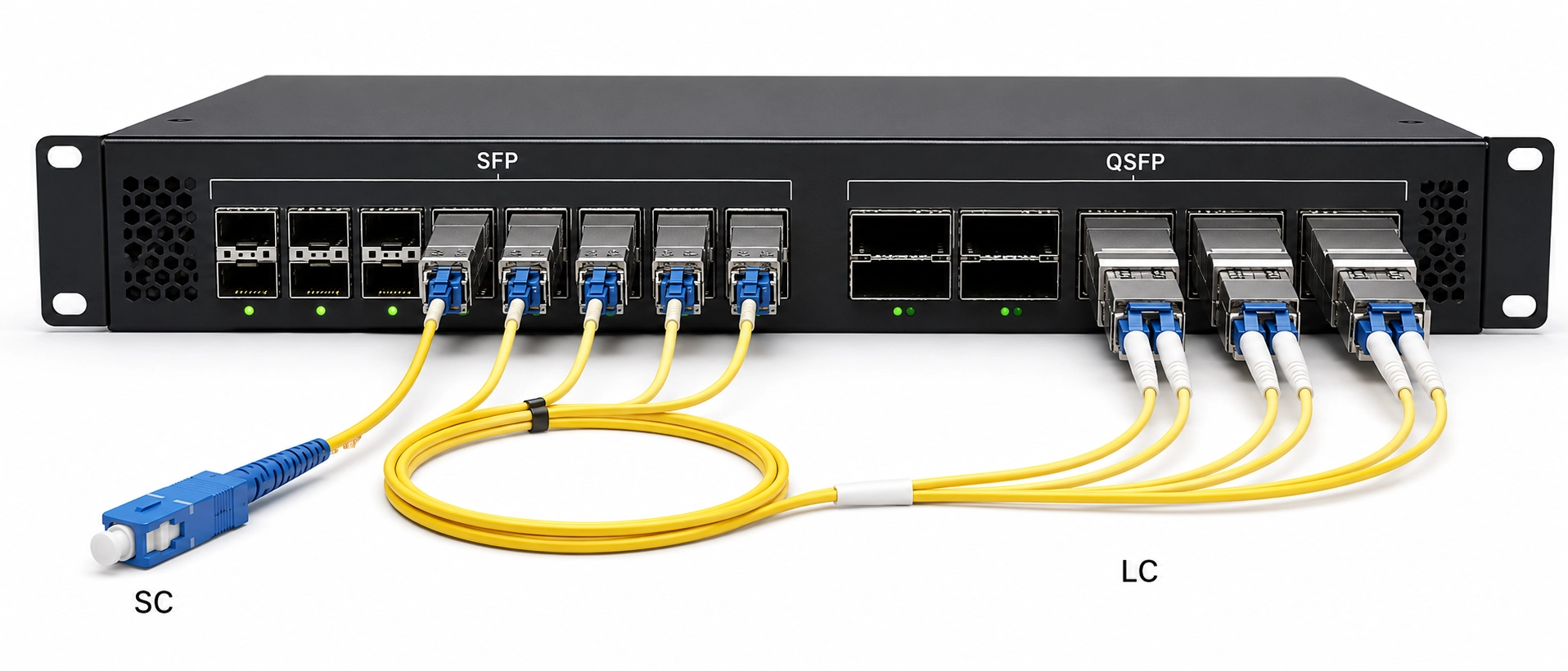
Once a mismatch is confirmed, decide whether the conversion belongs in an adapter, a hybrid patch cord, or the permanent pigtail. The correct location minimizes unnecessary mating points and keeps replaceable equipment separate from the permanent cabling layer.
- Use a same-interface adapter or ordinary patching when panel and equipment already share the required connector and polish.
- Use a hybrid patch cord when a permanent SC panel must serve replaceable LC equipment and keeping the conversion outside the splice tray improves maintenance.
- Re-splice the correct pigtail when the permanent termination itself is wrong and stacked conversions would add loss, inaccessible joints, or recurring service confusion.
- Retain a documented hybrid adapter in legacy ST/SC/FC infrastructure when the optical specification is correct and redesign is not justified.
The general answer is: adapters suit deliberate interface conversion; hybrid patch cords often suit the boundary between permanent panels and replaceable equipment; re-splicing suits an incorrect permanent termination.
But this conclusion can reverse when an added mating point breaks the loss budget, APC/UPC is mixed, FC keying is wrong, or the adapter conceals a fiber/optic mismatch. Those project variables must be resolved before the BOM is frozen.
Four "It Fits" Failures and How to Isolate Them
1. LC housing correct, SFP polish wrong
Conclusion: an LC pigtail is not approved for an LC optical module until the module's required polish is confirmed.
Field signal: the connector seats, but the module documentation specifies a different mating interface or the link shows abnormal loss/reflectance.
Check: use the full module part number. Cisco publishes connector and fiber type by module, and its compatibility matrix identifies LC (UPC) for relevant optics; the family name or cage alone is not enough. (Cisco Optics-to-Device Compatibility Matrix)
2. SC-to-LC conversion correct, BiDi pair wrong
Conclusion: an SC to LC fiber adapter compatibility check ends at the passive interface; it does not prove that the two BiDi modules are complementary.
Field signal: the passive path is continuous and every connector seats, but the link never establishes.
Check: compare the exact TX and RX wavelengths at both endpoints. If both ends transmit and receive on the same sides of the pair rather than complementary wavelengths, replace or re-pair the optics, not the adapter.
3. Connector and polish correct, fiber mode wrong
Conclusion: LC/UPC-to-LC/UPC can still be the wrong link when the optic and installed fiber mode do not agree.
Field signal: connector and polish inspections pass, yet receive power, reach, or link behavior is outside the expected design.
Check: read the transceiver's fiber/reach specification and verify the installed OS/OM designation from records or testing. Jacket and connector color are not sufficient evidence.
4. FC/APC label correct, keying overlooked
Conclusion: "FC/APC" can be incomplete for instruments that specify a narrow- or wide-key interface.
Field signal: the connector appears mechanically acceptable, but coupling or measurement repeatability is unstable.
Check: verify both connector key and mating sleeve. Thorlabs warns that a wide-key slot can be mechanically compatible with a narrow-key FC/APC connector yet fail to align the angled end faces correctly; its FC/APC connectors specify 2.0 mm narrow keys for relevant products. (Thorlabs mating sleeves; Thorlabs FC/APC connectors)
If a link fails after the connector fits, stop changing adapters at random. Move to the next failed gate and document the evidence that clears each earlier gate.
Pre-Connection Verification Checklist
A purchase-ready checklist should let the supplier, installer, and commissioning engineer reach the same conclusion independently.
| Verification field | Record before ordering |
|---|---|
| Equipment | Manufacturer and exact model/module SKU |
| Port | Port label, installed transceiver or removable adapter, and physical interface |
| Connector | LC / SC / FC / ST / E2000 / other |
| Polish | PC / UPC / APC at every mating point |
| Fiber | SM/MM and required OS/OM designation |
| Optic | Exact transceiver or optical subsystem |
| Wavelength | TX/RX wavelength or operating range |
| Architecture | Simplex / duplex / PON / other |
| Polarity | Required TX-to-RX mapping |
| Adapter | Same-interface or hybrid; connector, polish, and keying |
| Pigtail | Connector, polish, fiber, buffer, and length |
| End face | Inspection before every mating |
| Acceptance | Project-specific IL/RL or link-level test method and limits |
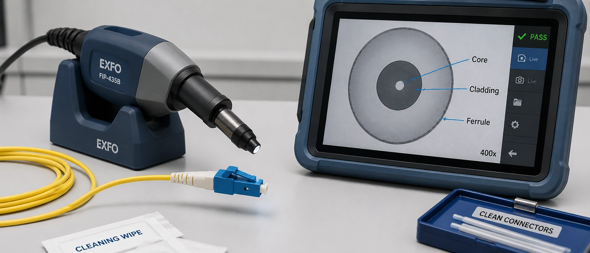
End-face inspection belongs in the workflow because a correct BOM can still show abnormal loss when a surface is contaminated. IEC 61300-3-35:2022 defines visual inspection procedures and criteria, but inspection does not replace attenuation, return-loss, or link qualification. (IEC 61300-3-35:2022)
For the practical inspection and test sequence, use our How to Test a Fiber Optic Pigtail procedure. The acceptance values themselves must come from the project loss budget, equipment limits, contract, and agreed test method; a generic checklist cannot set them for every link.
Do not send an RFQ that says only "500 pcs LC pigtails." In a 500-piece order, omitting the polish from one line item exposes all 500 terminations to the same approval error; the unit price does not recover the re-splicing and recommissioning work. State the intended equipment or panel, LC/UPC or LC/APC, OS2/OM designation, buffer construction, length, inspection/testing requirement, and any adapter or patch-cord interface.
Our 9-spec fiber pigtail RFQ framework covers the purchasing fields after compatibility is established. If your module or instrument is unusual, send the full model and port-path information with the checklist; we can flag the fields a generic matrix cannot resolve.
Before You Order: Send the Port, Not Just "LC" or "SC"
Start the inquiry with the installed system. Send us:
- equipment manufacturer and exact model/module;
- port or removable-adapter specification;
- existing fiber and panel/adapter path;
- optic, wavelength pair, and simplex/duplex architecture;
- required inspection and IL/RL or link acceptance criteria.
We will use those inputs to work backward through equipment port → patching interface → adapter → pigtail connector/polish → fiber → splice and provide a compatible BOM route plus a list of assumptions that still need confirmation. This review does not replace the equipment manufacturer's specification or site acceptance testing.
Once the gates are known, review the available fiber optic pigtail configurations for the permanent termination. If the installed panel and equipment need different interfaces, evaluate the fiber pigtail adapter compatibilityas part of the full connection path, not as an isolated part number.
The purchase target is not an adapter that lets two housings connect. It is a mechanically correct, optically compatible, maintainable path that can be verified before installation.
FAQ
Can SC, FC and ST fiber pigtail connectors be connected to each other?
Yes, they can be cross-mated through appropriate hybrid adapters, but connector housing, polish, fiber type and optical-system requirements must still match.
Can I connect an LC/APC pigtail directly to an LC SFP port?
Not from the LC label alone; the exact transceiver specification must confirm that the port supports the APC mating interface.
Does an SC-to-LC adapter solve single-mode, multimode or wavelength incompatibility?
No. An SC-to-LC adapter changes the physical mating interface and does not convert fiber mode, optical wavelength or BiDi TX/RX requirements.
Can a fiber assembly use APC on one end and UPC on the other?
Yes, a deliberately designed hybrid assembly can use different end specifications when each end mates correctly with its own interface; APC and UPC should not be directly mated to each other.
How should I verify a fiber pigtail before connecting it to equipment?
Verify the equipment port, connector, polish, fiber mode, optic/wavelength, architecture and polarity, then inspect the end face before mating and complete the required optical tests.