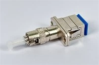
We write this guide for telecom engineers, network contractors, and enterprise buyers who evaluate physical connections across complex networks. Choosing single-mode patch cords requires more than reading basic parameter lists. Engineers must understand the physical rules that govern link budgets. This guide looks at the main engineering trade-offs across different deployment settings. It also offers practical checklists based on factory standards from suppliers like EVOLUX Fiber.
Why Single Mode is Winning the Future-Proofing Debate
Network architects report that single mode setups cost less over a building's full lifespan. Active transceiver gear costs more at first. Even so, the total cost of ownership stays lower. This shift happens because cabling stays inside the walls for 15 to 20 years. In contrast, teams replace active switches every three to five years. Single mode fiber uses a tiny core measuring 8 to 10 microns across. This narrow glass path forces light to travel in a single straight line along the center. It eliminates modal dispersion entirely. Modal dispersion happens when light rays travel at different angles, arrive at different times, and blur the signal.
| Specification | Value | Application Standard / Impact |
| OS2 Core / Cladding | 9/125 µm | Standard single-mode strand dimension |
| OS2 Maximum Attenuation | 0.4 dB/km | Long-haul signal retention |
| OS1 Maximum Attenuation | 1.0 dB/km | Legacy indoor trunk limit |
| OS2 Reach Limit | 200 km | Maximum optical run length |
| OS1 Reach Limit | 10 km | Campus-scale maximum link span |
| Installation Bend Radius | 20x cable diameter | Minimum radius under active pulling tension |
| Post-Install Bend Radius | 10x cable diameter | Long-term static routing limit |
| Max Patch Cord Loss | 0.75 dB | TIA insertion loss compliance ceiling |
| OS2 Standards | ITU-T G.652C, G.652D | Low water peak single-mode compliance |
| OS1 Standards | ITU-T G.652A, G.652B | Standard single-mode legacy compliance |
| OS2 Temperature Range | -20°C to +70°C | Rated operating thermal environment |
| LC Ferrule Outer Diameter | 1.25mm | Ceramic SFF connector interface |
| SC Ferrule Outer Diameter | 2.5mm | Standard push-pull connector interface |
| APC Endface Polish | 8-degree angle | Angled physical contact return loss control |
Many senior engineers on forums say you should never use multimode for structured cabling. We note this is experienced community advice rather than a mandatory rule. Bandwidth demands keep growing to support cloud tools and dense server setups. This push speeds up the move toward single mode. Recent discussions show that 100G/400G links require single mode fiber to keep signals clean over real-world distances. However, official reach limits still depend on the transceivers chosen by the architect. Better factory yields and higher production volumes continue to drop single mode optics prices. This makes it much easier for corporate buyers to pick one standard cable type.
Understanding OS2 fiber patch cable specifications
Network operators rarely use older fiber types in new builds today. Instead, they standardize on low water peak glass to support wavelength division multiplexing. Global standards classify these optical traits based on how glass absorbs and scatters light across the spectrum. OS1 fiber follows the ITU-T G.652A and G.652B standards. These cables show a sharp signal loss spike near the 1383 nm wavelength. This spike happens because hydroxyl ions get trapped in the glass during manufacturing. Modern OS2 fiber follows the ITU-T G.652C and G.652D standards. These standards eliminate the water peak and open the full spectrum for data traffic.
The glass size is the same in both types. An os2 single mode fiber patch cable uses a core and cladding size of 9/125 µm. The real difference shows up in signal loss over distance. OS1 fiber has a maximum loss of 1.0 dB/km. This high loss limits its use in modern wide area networks. In contrast, OS2 fiber has a maximum loss of 0.4 dB/km. Signals can travel much farther before they become too weak for the receiver to read. Because of these loss rates, OS1 reaches a maximum distance of 10 km under standard conditions. OS2 reaches up to 200 km before it needs an active signal booster. Engineers often say OS2 is better than OS1. Keep in mind that this is practical advice based on loss data, not a formal definition.
| Specification Category | OS1 Fiber Parameters | OS2 Fiber Parameters |
| Governing International Standard | ITU-T G.652A and G.652B | ITU-T G.652C and G.652D |
| Core to Cladding Diameter | 9/125 µm | 9/125 µm |
| Maximum Attenuation Limit | 1.0 dB/km | 0.4 dB/km |
| Maximum Transmission Distance | 10 km | 200 km |
| Primary Application Environment | Legacy Indoor Premises | Modern Outdoor and Long-Haul |
Application-Specific Selection: FTTH, 5G, and Enterprise Networks
Different deployment jobs bring distinct physical and environmental hurdles. Engineers must choose exact fiber sub-types to ensure lasting reliability. Standard long-haul networks typically use ITU-T G.652.D fiber. It provides very low loss on straight runs, but it loses signal if bent too tightly. Fiber to the home networks require routing cables around sharp indoor corners. These runs need bend-insensitive fiber that meets the ITU-T G.657.A1 or G.657.A2 standards. These designs change the cladding layer to trap light inside the core, even when the cable bends sharply.
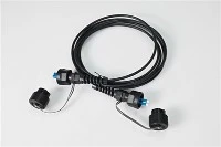
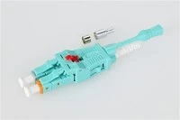
Cellular 5G networks place fiber links at the top of radio towers. These runs expose patch cords to extreme heat, cold, sun, and wind vibration. Tower fronthaul setups need tough, armored cables with weather-resistant outer jackets. These jackets stop water from getting inside and ruining the glass. Data centers face a very different challenge. They must fit many cables into tight equipment racks while keeping airflow open. Buyers often choose slim uniboot patch cords for these rooms. A uniboot design packs two fiber strands into a single round jacket about 2.0mm wide. Makers like EVOLUX Fiber build custom jackets, glass grades, and connectors for each specific job.
| Deployment Scenario | Typical Cable Configuration | Mandatory Engineering Specifications |
| Fiber to the Home | Simplex drop cables with internal aramid yarn | ITU-T G.657.A1 or G.657.A2 bend-insensitive glass |
| 5G Tower Fronthaul | Armored duplex cables with pulling eyes | UV-resistant outdoor jacket with water-blocking tape |
| Enterprise Data Center | Uniboot duplex cables with push-pull tabs | LSZH or OFNP fire-rated indoor jacket materials |
Connector Configurations: LC vs SC, UPC vs APC, and Polarity
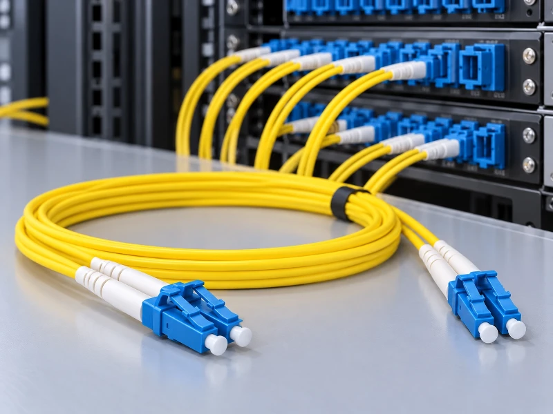
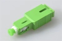
Wrong connector types cause a large share of optical link failures. Designers must pick the right shape and polish angle every time. The market mainly relies on two connector types for single-mode fiber optic patch cables single mode. Each style fits different rack space needs. The LC connector uses a 1.25mm ceramic ferrule. This small size lets engineers fit twice as many ports onto a switch panel. The SC connector uses a larger 2.5mm ceramic ferrule. It offers a sturdy grip that field workers still prefer when working in outdoor boxes with heavy gloves.
The shape of the glass tip controls how the connector handles reflected light. Reflected light can damage laser transmitters if it travels backward into the fiber core. Ultra physical contact (UPC) connectors use a slightly curved tip. This shape pushes the glass cores together directly, giving a return loss of about -50 dB. APC connectors use an 8-degree angled tip. The angle shoots reflected light straight into the cladding instead of back toward the laser source. This gives a return loss better than -60 dB. Plugging an APC connector into a UPC connector leaves an air gap. This gap can crush the glass tips, causing permanent hardware damage and dropping the link. When joining mismatched ports, engineers must use hybrid patch cables with UPC on one end and APC on the other.
Duplex links must line up the transmit and receive lines across the whole run. This setup is called polarity.
Method A uses a straight wiring layout where fiber one plugs into position one on both ends, which requires a flip cable at one end to cross the signals properly.
Method B crosses the lines directly so fiber one connects to position two on the other end, lining up the paths automatically without extra custom cables.
Method C crosses wire pairs inside the trunk cable, which works well for basic duplex links but creates layout issues when upgrading to parallel optics later.
Critical Installation Tolerances: Bend Radius and Environmental Ratings
Exceeding cable bend limits during installation causes lasting signal loss and can create safety hazards. Bending a fiber cable too sharply ruins total internal reflection. The light hits the outer glass boundary at the wrong angle. This issue is called macrobending loss. Light leaks out of the core and gets lost in the cladding, creating a local fault that forces you to replace the run. To stop this from happening, keep the bend radius above 20x the cable diameter while pulling. Once the cable rests inside the frame, keep the long-term bend radius above 10x the cable diameter.
Safety codes and fire laws dictate what plastics makers must use for outer cable jackets. The operating temperature range for OS2 fiber is -20°C to +70°C. This range covers both air-conditioned data halls and harsh outdoor cabinets. Network designers must choose the right flame rating to pass building inspections.
Low Smoke Zero Halogen jackets give off very little toxic smoke during fires, making them mandatory in underground tunnels and many European facilities.
Optical Fiber Nonconductive Riser jackets include fire-retardant materials that stop flames from climbing between floors through vertical building shafts.
Optical Fiber Nonconductive Plenum jackets carry the highest fire rating, which building codes require whenever cables run through open air spaces above drop ceilings.
Optical Link Budget and Insertion Loss Limits for Single Mode Patch Cables
Reliable networks require careful link budget planning. You must track every part that weakens the light signal. A standard link budget calculation takes the lowest transmitter power and subtracts the minimum receiver sensitivity. This gives you the total allowed optical loss for the channel. Engineers add up the loss from the fiber run, splices, and patch connectors. The total loss must stay below the allowed budget with a safety margin of at least 2.0 dB. The TIA standard allows up to 0.75 dB of insertion loss per patch cord. Top suppliers build cables that test far below this limit. Consider setting a 0.2 dB loss limit for data center patch cords to save budget for long backbone runs.
Dirty connector tips cause high signal loss and dangerous back reflections. Technicians must inspect every tip before plugging it into an active switch. A single dust speck trapped between two ceramic ferrules can scratch the glass. It can also embed itself into the core, ruining both the patch cable and the expensive transceiver optic.
Inspect the connector end-face using a digital fiber microscope that runs automated pass-fail tests.
If the tool finds dirt on the core or cladding, clean the tip with a dry, lint-free tool sized for 1.25mm or 2.5mm ferrules.
Inspect the connector again with the digital tool to make sure all dirt is gone and no residue remains.
Plug the clean connector into the port immediately so floating room dust cannot settle on the glass.
Test the finished link with an optical time domain reflectometer to measure channel loss and check for sharp bends.
B2B Procurement: Supplier Evaluation Checklist and RFQ Template
Smart purchasing means looking past sales claims. You must ask for test data and exact physical build details from your supplier. Low-cost vendors often claim they meet international standards. Yet, many skip the quality controls needed to keep connector tips uniform across large runs. Buyers can use trusted makers like EVOLUX Fiber as a quality benchmark. Reliable vendors include interferometer test sheets with each batch to prove their insertion loss and return loss numbers. Reject bids from vendors who refuse to provide batch test data, or who substitute OS1 glass in cables labeled as standard single mode.
Engineers must list every physical and optical spec when writing a request for quotation. This stops vendors from making assumptions that could compromise the build.
Supplier Evaluation Checklist
Does the supplier operate a vertically integrated manufacturing facility, or do they simply re-label cables purchased from secondary markets?
Can the supplier provide sample interferometer test reports demonstrating compliance with IEC end-face geometry standards for radius of curvature and apex offset?
Does the facility hold current ISO 9001 certification for quality management and ISO 14001 certification for environmental compliance?
What is the standard lead time for custom lengths, and does the supplier maintain local inventory for emergency replacement orders?
Does the supplier use genuine Corning or equivalent tier-one glass, or do they source unbranded bare fiber from commodity markets?
RFQ Specification Template
To get accurate prices and the right products, copy these items into your quote request and update the values to match your project needs.
Fiber Category: Specify ITU-T G.652.D for standard runs or ITU-T G.657.A2 for bend-insensitive requirements.
Connector Configuration End A: Specify form factor and polish (e.g., LC/UPC).
Connector Configuration End B: Specify form factor and polish (e.g., SC/APC).
Cable Construction: Specify simplex, standard zip-cord duplex, or round uniboot duplex.
Jacket Material and Diameter: Specify the fire rating (e.g., LSZH, OFNR, OFNP) and the physical diameter (typically 1.6mm, 2.0mm, or 3.0mm).
Optical Performance Limits: Demand a maximum insertion loss of 0.2 dB and a minimum return loss of 50 dB for UPC or 60 dB for APC.
Length and Tolerance: Specify the exact length in meters, requesting a tolerance of plus 10 centimeters and minus zero centimeters to prevent short cables.
Documentation Requirements: Require printed test labels attached to every cable bag and a digital spreadsheet containing the test results for the entire batch.
Order Quantity and Packaging: Specify the total number of units and request plastic-free bulk packaging if your facility mandates waste reduction protocols.
Frequently asked questions
Q: Are OS1 and OS2 fiber compatible?
A: OS1 and OS2 fiber are optically compatible because both share the same 9/125 µm core and cladding size. Both work with standard single-mode optical formats. OS1 follows ITU-T G.652A and G.652B standards, while OS2 meets ITU-T G.652C and G.652D rules. You can join them directly with 1.25mm LC or 2.5mm SC connectors. Just make sure your link budget accounts for the higher signal loss in the older OS1 cable sections.
Q: Can you mix OS1 and OS2 fiber?
A: You can mix OS1 and OS2 fiber in the same network run, but the weaker cable will limit overall performance. OS1 has a maximum loss of 1.0 dB/km, which is much higher than the 0.4 dB/km limit of OS2. So, adding OS1 into an OS2 link pulls the total reach down toward the 10 km limit of OS1. This prevents the run from reaching the 200 km range that a full OS2 setup supports.
Q: Is OS2 multimode or singlemode?
A: OS2 is singlemode optical fiber built for long-distance, high-speed data links. The cable uses a 9/125 µm build. The light-carrying core measures 9 microns across inside a 125-micron outer cladding, fitting right within the standard 8 to 10 microns range for singlemode glass. This thin core allows only one light path to travel. That stops modal dispersion and lets OS2 deliver low loss rates of 0.4 dB/km over distances up to 200 km.