A fiber optic termination box should be selected after the termination architecture is defined, not simply by counting ports.
The enclosure has to support the incoming cable, the selected splice or connector method, fiber routing, splice protection, adapter interfaces, slack storage, maintenance access, and the environmental conditions of the installation. A box that matches the required port count can still be unsuitable if those internal requirements do not fit together.
"Fiber optic termination" is broader than the box itself. It covers the connections used to end or join fibers. In this article, termination box and enclosure may refer to the same housing where the context is clear; termination continues to mean the wider connection process.
For network engineers, integrators, contractors, and technical buyers, the design sequence is:
define the connection architecture → define cable and interface requirements → verify internal layout → verify environmental evidence → define acceptance testing.
What Fiber Optic Termination Actually Includes
Fiber termination is not synonymous with a termination box. The Fiber Optic Association distinguishes connectors, which create demountable connections, from splices, which create permanent fiber joints. The method chosen therefore affects what the box must accommodate. ([The Fiber Optic Association][4])
| Element | Primary role | Main design question |
|---|---|---|
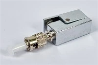
| Connector | Creates a demountable optical interface | Which connector family, polish, fiber type, and mating interface are required? |
| Fusion or mechanical splice | Joins fibers | How will the joint be made, protected, stored, and tested? |
| Pigtail | Provides a factory-terminated connector with spliceable fiber | Does its connector, polish, fiber type, buffer construction, and length match the design? |
| Termination box | Protects and manages cable entry, splices, adapters, fiber slack, and service access | Can the enclosure support the complete termination architecture? |
A patch panel, splice closure, distribution box, and termination box can overlap in function, but they should not be treated as automatic synonyms. The network position and required functions determine which type of hardware is appropriate.
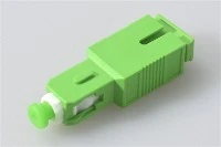
For pigtail-based designs, connector matching should be confirmed before the enclosure layout is finalized. Connector family, APC or UPC polish, fiber mode, and the mating interface all affect compatibility. For a detailed interface check, see EVOLUX's fiber pigtail connector compatibility guide.

Where a Termination Box Fits in the Network
In FTTH, ODN, building-entry, and equipment-room applications, a termination box acts as a managed transition point.
Depending on the architecture, it may need to:
- secure the incoming cable so movement or pulling force is not transferred directly to fibers;
- protect fusion or mechanical splice points;
- store fiber slack within the routing limits of the actual fiber and cable construction;
- present connector interfaces through adapters;
- provide controlled access for identification, testing, repair, and later changes.
This is why port count alone is not a sufficient sizing rule.
For example, a nominal 12-port box may still be unsuitable if the selected cable cannot be anchored correctly, the splice tray cannot hold the required splice protection, a splitter occupies the intended storage area, or fiber routing becomes too tight after all components are installed.
ITU-T G.657 defines categories of bend-insensitive single-mode fiber for access and related networks. Its scope also illustrates why bend behavior must be considered in relation to the actual fiber category and product rather than one universal routing number. ([ITU][5])
The useful design sequence is therefore:
network position → termination method → cable and fiber construction → internal routing → enclosure configuration.
Choose the Termination Method Before the Box
The termination method changes the tools, internal space, optical path, field workflow, and repair strategy.
Selecting the enclosure first can create a configuration problem later. A box initially chosen around adapter count may appear adequate for direct field connectors. If the project later changes to fusion-spliced pigtails, the same enclosure must now accommodate splice protection, tray positions, pigtail routing, and additional slack. The port count has not changed, but the internal requirements have.
Pigtail fusion splicing
With this architecture, a factory-terminated pigtail is fusion-spliced to the field fiber. The splice is protected and stored, while the connector is presented through an adapter.
The enclosure normally has to account for:
- splice-tray positions;
- splice-protection storage;
- pigtail routing;
- incoming fiber routing;
- connector and adapter compatibility;
- technician access to the splice and connector sides.
FOA describes factory-made pigtail splicing as one of the common approaches used for field single-mode termination. ([The Fiber Optic Association][4])

Pre-polished or field-installable connector
Some field-installable connectors include an internal mechanical splice. Installation speed alone is not a sufficient comparison criterion.
The total termination includes both a connector interface and the internal splice, and successful installation depends on factors such as cleave quality, tools, connector process, and technician training. FOA notes that splice loss is affected by cleave quality and that these connector systems rely on the appropriate termination process. ([The Fiber Optic Association][15])
For enclosure selection, the practical questions are whether there is sufficient working access for the connector system, whether cable and fiber strain relief can be maintained, and whether the completed connection can be inspected and tested using the project's acceptance method.
Fusion splice-on connector
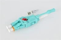
A fusion splice-on connector uses a factory-prepared connector assembly that is fusion-spliced to the field fiber.
It should be treated as a system choice rather than simply another connector type. FOA's splice-on connector reference describes a connector-specific holder used with the cleaver and fusion splicer. Compatibility therefore needs to cover the connector, holder, splicer process, fiber type, and enclosure access required by that system. ([The Fiber Optic Association][15])
Pre-terminated cable or enclosure
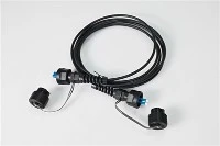
A factory-terminated assembly can move some termination work away from the deployment site, which can be useful where field access or installation windows are constrained.
The trade-offs move elsewhere:
- cable length must be planned accurately;
- terminated connectors require protection during pulling and handling;
- pathways must accommodate the assembly;
- excess cable must be managed;
- connector interfaces become part of the optical path;
- factory configuration and project lead time become part of planning.
FOA similarly identifies cable-length accuracy and connector protection as issues that have to be considered with preterminated cable. ([The Fiber Optic Association][4])
That does not make pre-terminated architecture universally faster or lower-cost. Any efficiency comparison needs a defined project baseline, product system, installation scope, and measurement method.
| Method | Main enclosure implication | Main field dependency | Evidence to confirm |
|---|---|---|---|
| Fusion-spliced pigtail | Tray capacity, splice protection, pigtail routing, slack | Fusion process and pigtail compatibility | Layout, connector specification, splice/test method |
| Field-installable connector | Working access and routing around connector termination | Cleave quality, tool condition, installation process | Connector-system documentation and acceptance method |
| Fusion splice-on connector | Splicing access plus connector presentation | Splicer, holder, connector, and fiber compatibility | Approved process and system compatibility |
| Pre-terminated assembly | Connector protection, pathway clearance, cable-length and slack planning | Factory configuration and installation pathway | Assembly drawing, handling limits, optical test documentation |
Choose among these methods by comparing the complete installation system, not by assuming that one method is always faster or produces one fixed loss value.
A Six-Input Selection Workflow
A useful fiber optic termination box specification starts with project inputs, not an enclosure feature list.
Six inputs cover most of the compatibility questions that should be resolved before an RFQ or technical approval.
1. Environment
Define the actual installation environment:
- conditioned indoor space;
- unconditioned indoor area;
- protected outdoor location;
- exposed outdoor location;
- wall or pole installation;
- building entrance or another location with specific mechanical or fire requirements.
"Indoor" and "outdoor" are useful categories, but they are not complete specifications. The environmental conditions and required qualification evidence still need to be defined.
2. Cable construction and entry
Confirm:
- cable construction and diameter;
- number and direction of cable entries;
- required gland or sealing arrangement;
- strength-member anchoring;
- strain-relief method;
- entry orientation;
- required service-loop arrangement.
The cable has to fit both the opening and the internal retention system. A gland size that accepts the cable diameter does not by itself prove that the complete anchoring and routing arrangement is suitable.
3. Fiber type and internal construction
Confirm the fiber family and the buffer or tube construction that will enter the box.
A 250 μm fiber arrangement and a 900 μm tight-buffered pigtail do not necessarily require the same handling and protection inside an enclosure. EVOLUX's current 250 μm vs 900 μm fiber pigtail guide provides additional background on those two constructions. ([Shenzhen Evolux Fiber Co., Ltd][13])
Routing limits should come from documentation for the actual fiber, pigtail, buffer tube, and cable rather than from a universal number copied into every specification.
4. Connector interface
Specify the complete interface.
Relevant inputs include:
- connector family;
- APC or UPC polish;
- single-mode or multimode fiber;
- adapter arrangement;
- downstream mating interface.
Writing only "SC" or "LC" leaves important compatibility information undefined.
5. Capacity
Capacity should represent the complete installed configuration, not just the number printed beside the adapter ports.
Account for:
- active adapter positions;
- required splices;
- splice-tray positions;
- splitter or other internal modules;
- incoming and outgoing cable paths;
- fiber slack;
- planned future circuits;
- technician access after the box is populated.
There is no evidence-based reason to apply the same fixed 25% or 50% reserve to every network.
Instead, derive the requirement from a defined growth case:
- record the fibers, splices, and ports required for the initial deployment;
- identify the expansion that is actually planned or reasonably specified by the network design;
- add the trays, adapters, splitters, and routing space that expansion would require;
- confirm on the complete enclosure layout that the expanded configuration can still be routed and serviced without obstructing existing fibers.
This produces an auditable capacity requirement without inventing a universal spare-port percentage.
6. Service access
Consider what a technician will need to do after commissioning.
Can an adapter be reached without disturbing unrelated fibers? Can a tray be opened without forcing another fiber path into a tighter bend? Are labels visible after full population? Can an additional approved connection be routed through the existing management path?
These questions often distinguish two enclosures that appear equivalent when only their external dimensions and port counts are compared.
Internal Design Details That Decide Field Reliability
Two termination boxes with the same nominal capacity can behave very differently once cable, trays, pigtails, adapters, and slack are installed.
Cable anchoring and strain relief
The incoming cable should be mechanically secured so normal cable movement is not transferred directly to individual fibers, splices, or connector interfaces.
When reviewing a design, check where the strength member is fixed, how the cable sheath is restrained, how the entry hardware is assembled, and whether the intended configuration matches the one covered by the supplier's technical documentation.
Bend routing
Do not write a procurement rule such as "every termination box must maintain at least 30 mm bend radius."
Corning's AEN021 distinguishes optical-fiber bend limits from optical-cable bend limits and states that the two should not be confused. It also directs users to the specific manufacturer's limits for the product involved. ([Corning][6])
ITU-T G.657 likewise addresses bend-insensitive single-mode fiber categories, but that does not make every G.657 fiber, pigtail, buffer tube, or cable interchangeable. ([ITU][5])
A stronger RFQ requirement is:
Provide the internal routing layout and confirm that the specified fiber, pigtail, buffer, and cable construction can be routed within their documented product limits.
Splice protection and tray layout
Check the number and type of splice-protection positions in the configuration that will actually be supplied.
Nominal port capacity does not automatically equal usable splice capacity. Adapter arrangements, splitters, trays, pigtails, and storage features can compete for the same internal space.
Slack storage
Slack is useful only when it can be stored without crossing moving parts, blocking trays, creating unsupported bends, or making later service difficult.
Review slack management with the complete intended configuration installed, not from an empty enclosure photograph.
Labeling and maintenance access
Labels should remain readable after the box is populated.
The internal layout should allow a technician to trace the incoming fiber, splice, adapter, and outgoing connection without unnecessarily disturbing neighboring circuits.
Environmental Ratings Require Evidence, Not Labels
An IP code is useful evidence, but it is not a complete environmental qualification.
IEC 60529 defines classification of the degrees of protection provided by enclosures for the conditions covered by the IP Code. The current IEC consolidated edition is IEC 60529:1989+AMD1:1999+AMD2:2013, Edition 2.2. ([IEC Webstore][7])
It does not by itself establish every other characteristic that may matter in an outdoor installation. For that reason, a statement such as "IP65" or "IP68" should not be treated as proof of every requirement involving UV exposure, material aging, temperature cycling, mechanical impact, fire performance, or a particular installed cable-entry arrangement.
For each environmental claim, ask what exact configuration was evaluated.

| Evidence check | Why it matters |
|---|---|
| Exact model/configuration | Prevents results from one enclosure being applied to another |
| Sample assembly state | Shows whether plugs, adapters, glands, and covers matched the deployed condition |
| Cable-entry configuration | Entry hardware can affect the environmental boundary |
| Standard and edition | Identifies the test framework |
| Test conditions and severity | Defines what the result actually covers |
| Test organization | Identifies the source of the evidence |
| Test date | Helps confirm the result applies to the current design |
| Result and acceptance criteria | Separates a documented test from a marketing label |
Environmental requirements can also exist at component level.
IEC 61753-021-03:2026 specifies minimum initial test and measurement requirements and severities for certain single-mode fiber-optic connectors terminated as pigtails or patchcords to meet Category OP, an outdoor protected environment. Its scope does not certify a termination box, but it illustrates why connector and enclosure evidence may need to be evaluated separately. ([IEC Webstore][8])
The practical procurement rule is simple: match each environmental claim to the exact component or enclosure, configuration, standard, and test evidence that supports it.
Inspection, Testing and Acceptance
A termination that looks complete is not necessarily an accepted optical connection.
IEC 61300-3-35:2022 covers visual inspection and classification of contamination, scratches, and defects on fiber-optic connector end faces. The standard explicitly states that visual inspection is in addition to, and does not replace, measurements of performance parameters such as attenuation and return loss. ([IEC Webstore][9])
A defensible acceptance workflow therefore separates inspection from optical measurement:
- inspect the connector end face using the applicable procedure;
- clean it when required;
- reinspect before mating;
- perform the optical tests required by the project specification;
- record the result against the required circuit, port, fiber, or enclosure identifier.
The acceptance limits themselves should come from the network design, contract, applicable product specification, or governing standard. A generic article should not invent universal Pass/Fail numbers.
The same distinction is useful for fusion splicing. A fusion splicer's estimated splice loss is process information; it should not automatically be treated as an independent measurement of the completed optical path.
FOA's testing reference describes loss testing with an appropriate source and power meter and identifies documentation fields including fiber identification, test equipment, reference method, wavelength, and measured loss. ([Fiber Optic Association][10])
For connector-specific inspection detail, see EVOLUX's fiber connector inspection guide. ([Shenzhen Evolux Fiber Co., Ltd][14])
A project acceptance record may need to identify:
- circuit or fiber ID;
- enclosure or termination ID;
- connector/interface;
- inspection result;
- test method;
- test wavelength;
- reference method;
- measured optical result required by the project;
- test equipment;
- date and operator;
- disposition of failures and rework.
The important point is traceability: a statement such as "100% tested" is much less useful than a defined test method and a record tied to the actual connection being accepted.
Deployment Risks and Safe Work Boundaries
Fiber termination work includes risks beyond optical performance.
FOA's safety guidance identifies small glass fiber scraps, potentially active fibers, chemicals used during termination and splicing, and conditions around fusion-splicing work as hazards requiring appropriate controls. ([Fiber Optic Association][11])
This article is a design and procurement guide, not a substitute for installation training or an employer's safety procedure.
Before work begins, the applicable company SOP should address topics such as:
- live-fiber status and optical safety;
- appropriate PPE;
- fiber-shard collection and disposal;
- cleaning-material handling;
- fusion-splicing equipment;
- housekeeping and work-area control;
- approved inspection and test procedures;
- escalation when the cable, connector, or enclosure does not match the approved design.
An unexpected site configuration should trigger a design or procedure check, not an improvised termination method.
What to Put in a Termination Box RFQ
A useful RFQ gives the supplier enough information to confirm an actual configuration.
"A 12-port outdoor fiber box" leaves too many engineering assumptions undefined.
Use the following fields as a starting point:
| RFQ input | Information to provide or request |
|---|---|
| Deployment location | Indoor/outdoor condition, mounting position, exposure, access constraints |
| Incoming cable | Construction, diameter, fiber count, strength member, entry direction |
| Fiber | Fiber type/category and relevant buffer or tube construction |
| Termination method | Fusion-spliced pigtail, field-installable connector, splice-on connector, pre-terminated assembly, or another defined architecture |
| Connector interface | Connector family, APC/UPC, fiber mode, adapter arrangement |
| Splice capacity | Required splice count and protection arrangement |
| Internal components | Splitters, additional trays, adapters, or other components consuming space |
| Routing and slack | Service-loop needs and documented routing limits |
| Mounting/service access | Wall, pole, rack, door access, labeling, maintenance constraints |
| Environmental evidence | Required IP or other environmental tests, with the applicable standard and configuration identified |
| Optical acceptance | Inspection and optical test requirements defined by the project |
| Documentation | Configuration drawing, component list, applicable test records, and traceability requirements |
| Sample requirement | Whether an assembled sample is required before volume approval |
| Change control | How substitutions or configuration changes must be approved |
Once these inputs are defined, the enclosure can be evaluated as a system instead of as a port count.
EVOLUX's current terminal-box range includes indoor and outdoor enclosures, wall- and pole-mounted formats, compact and multi-core distribution boxes, pre-connectorized options, and project-specific configurations that may be assembled with adapters, pigtails, splice trays, PLC splitters, and mounting accessories. ([Shenzhen Evolux Fiber Co., Ltd][2])
Use the EVOLUX fiber optic terminal box range to identify candidate formats, then check the candidate against the project's cable construction, termination method, connector interface, internal-space requirements, mounting arrangement, and required acceptance evidence.
For a project review, submit the deployment environment, cable construction, fiber count, connector interface, mounting method, termination architecture, and acceptance requirements. Ask for confirmation of the model-specific configuration and the documentation available for that exact configuration, rather than relying on unsupported statements such as "outdoor rated" or "100% tested."