The Decision in One Minute
For most standard ODFs, termination boxes, and low-to-medium-count single-fiber splicing, the 250um vs 900um fiber pigtail decision should start with 900µm. It is easier to handle around the connector and routing area. When splice-cassette density, mass-fusion layout, or restricted routing space becomes the limiting factor, 250µm is usually the better starting point.
Buffer diameter is a mechanical construction choice, not an optical grade. A 900µm fiber pigtail does not inherently produce lower splice loss than a 250µm pigtail, and a 250µm fiber is not optically inferior because it is thinner.
That changes the engineering question. Instead of asking which diameter performs better, ask which fiber presentation fits the tray, handling workflow, splice method, and mechanical protection available in the installation.
What 250µm and 900µm Actually Measure
A typical telecom single-mode fiber can be simplified as:
~9µm core → 125µm cladding → ~250µm primary coating → optional ~900µm buffer
The 250µm dimension normally refers to the coated optical fiber. A 900µm construction adds another protective layer around that coated fiber. The underlying optical fiber can still be the same fiber type.
This is why the common search phrase 250um loose tube vs 900um tight buffer needs qualification. A 250µm coated fiber is frequently found inside loose-tube cables, while 900µm tight-buffered fiber is common in indoor termination assemblies. Diameter alone, however, does not define the complete cable construction.
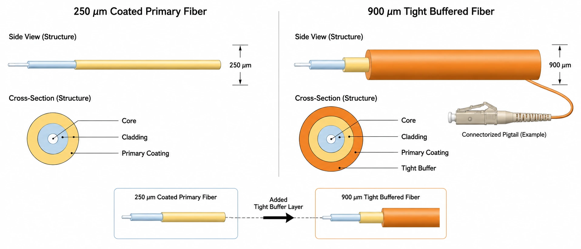
250µm vs 900µm Pigtail Construction at a Glance
| Engineering factor | 250µm fiber pigtail | 900µm fiber pigtail |
|---|---|---|
| Optical glass | Can use the same SM/MM fiber type | Can use the same SM/MM fiber type |
| Cladding diameter | Typically 125µm | Typically 125µm |
| Outer presentation | Primary coated fiber | Additional buffer around coated fiber |
| Handling | More delicate | Easier to handle individually |
| Mechanical protection | Relies more heavily on tray/enclosure | Better protection during routing and preparation |
| Tray density | Higher | Lower |
| Stripping workflow | Less material to remove | Depends strongly on buffer construction |
| High fiber-count cassette | Often advantageous | Can consume unnecessary routing volume |
| Mass fusion/ribbon workflow | Better aligned with many dense architectures | Usually less attractive |
| Standard ODF termination | Usable, but protection must be designed in | Usually the practical default |
The raw geometric difference is larger than the diameters initially suggest. If two circular constructions are compared only by diameter, their cross-sectional areas scale with the square of the diameter:
(900 / 250)² ≈ 12.96
That does not mean a tray can hold exactly 13 times as many 250µm fibers. Splice sleeves, bend requirements, slack loops, retainers, and fiber crossings also consume space. The calculation explains why replacing many 250µm routing sections with 900µm sections can affect a high-count tray much more than the diameter numbers alone suggest.
Buffer Size Does Not Set Your Optical Performance
Buffer diameter does not determine insertion loss. During fusion splicing, the relevant optical interface is the prepared glass fiber. The coating or buffer is removed from the splice region before the cleaved fibers are aligned and fused.
The Fiber Optic Association describes single-mode fusion-splice loss as typically 0.1 dB or less. Higher loss can point to problems such as contamination or an imperfect splice. That remains a splice-quality issue, not evidence that a 900µm buffer transmits light better than a 250µm coating. (Fiber Optic Association)
Do not accept "900µm for lower loss" as a meaningful RFQ specification.
Instead, confirm that the optical fibers being joined are compatible. Fiber type and, where relevant, mode-field characteristics matter much more than the outside buffer diameter. The wider preparation context is covered in our fiber cable termination methods guide.
Can You Fusion Splice 250µm Fiber to a 900µm Pigtail?
Yes. A 250um fiber to 900um pigtail transition is a normal architecture when the underlying optical fibers are compatible.
The fusion splicer is not welding "250µm material" to "900µm material." Both protective constructions are stripped from the splice region. The glass is cleaned and cleaved, the prepared fibers are aligned and fused, and the finished splice is protected before being stored in the tray.
FOA illustrates this directly with a 24-fiber outside-plant cable in which 250µm fibers are spliced to color-coded 900µm pigtails for termination. (Fiber Optic Association)
The real condition is optical compatibility. If two fibers have different mode-field or backscatter characteristics, an OTDR can show different apparent splice losses depending on test direction. Bidirectional measurement helps characterize that situation correctly. (Fiber Optic Association)
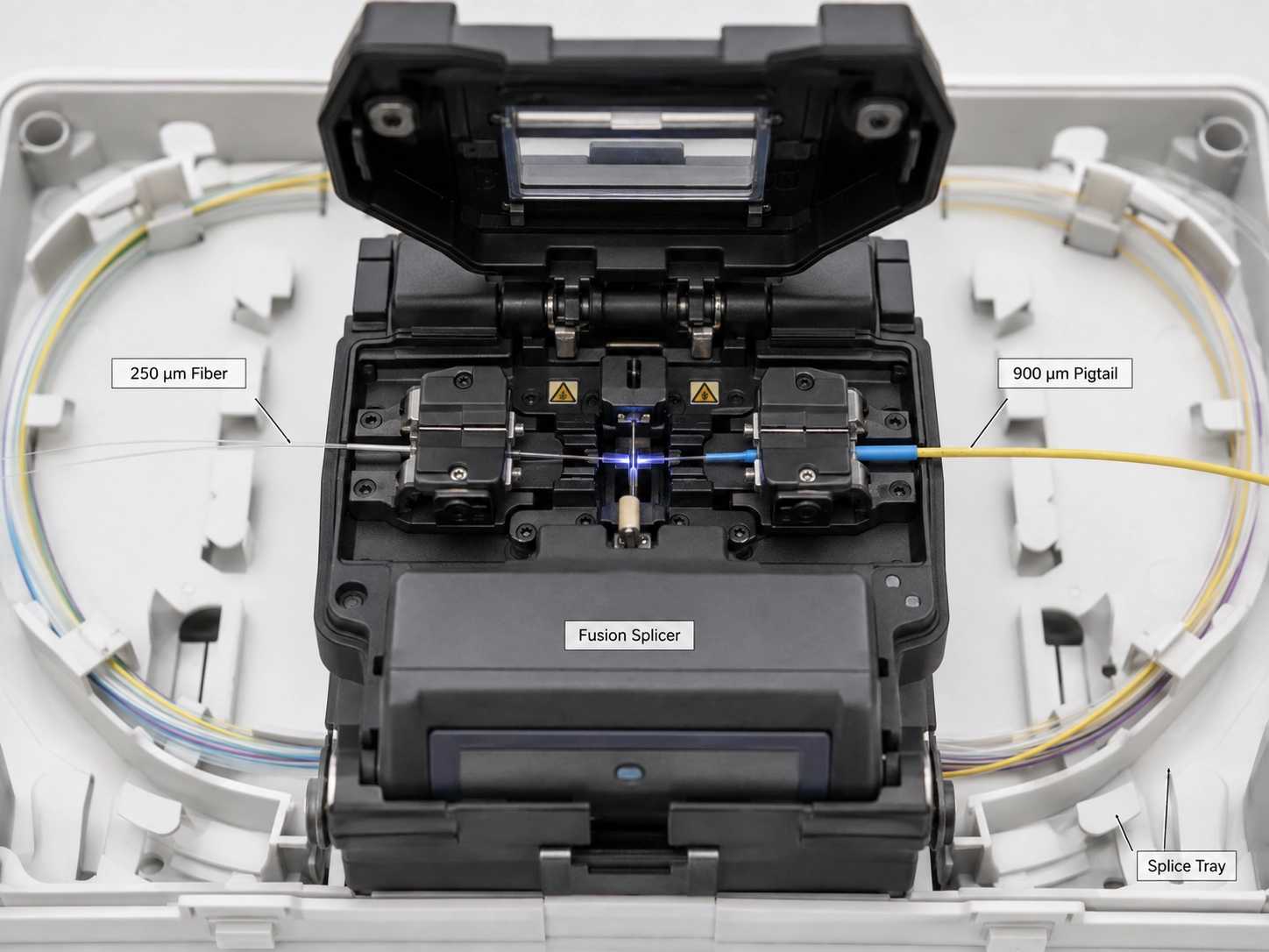
A procurement specification therefore should not reject a 250µm-to-900µm architecture simply because the outside diameters differ.
When a 900µm Fiber Pigtail Is the Better Engineering Choice
A 900um fiber pigtail for fusion splicing is the practical starting point in a normal ODF or termination box when routing space is available and technicians handle fibers individually.
Standard ODF and Telecom Termination
For LC termination in an ODF, a 900µm pigtail usually provides more useful individual-fiber protection than a 250µm presentation when the tray has sufficient routing space. This is the practical application behind an LC fiber pigtail for ODF specification, rather than simply choosing 900µm because it is thicker.
There is an important boundary. A 900µm buffer is not equivalent to a 2.0 or 3.0mm jacketed patch cord. If fiber leaves the protected tray and will be repeatedly pulled, tied, repositioned, or exposed to equipment handling, appropriately jacketed or otherwise protected cordage is the safer specification.
Low-count Termination Boxes
At modest fiber counts, saving routing volume is usually not the dominant constraint. If the tray already provides a protected routing path, 900µm generally makes installation and later identification easier.
That default stops working when the additional buffer causes fiber crossings, compressed slack storage, or interference with the tray cover. At that point the enclosure geometry has become the controlling variable.
When 250µm Pigtails Make More Sense
A 250um fiber pigtail becomes the stronger choice when routing density is the constraint and the enclosure itself provides the required mechanical protection.
High-density Splice Cassettes
In a protected fiber pigtail for splice cassette design, 250µm routing reduces the volume occupied by individual fibers and leaves more room around splice holders and slack-storage paths.
This is where the 12.96× geometric comparison becomes useful. It does not predict cassette capacity. It explains why a 650µm difference in diameter becomes important when repeated across many individual routing sections.
The condition is mechanical protection. A 250µm coated fiber should remain inside a controlled fiber-management path. Moving unprotected 250µm fiber outside the cassette merely exchanges a density problem for a mechanical-risk problem.
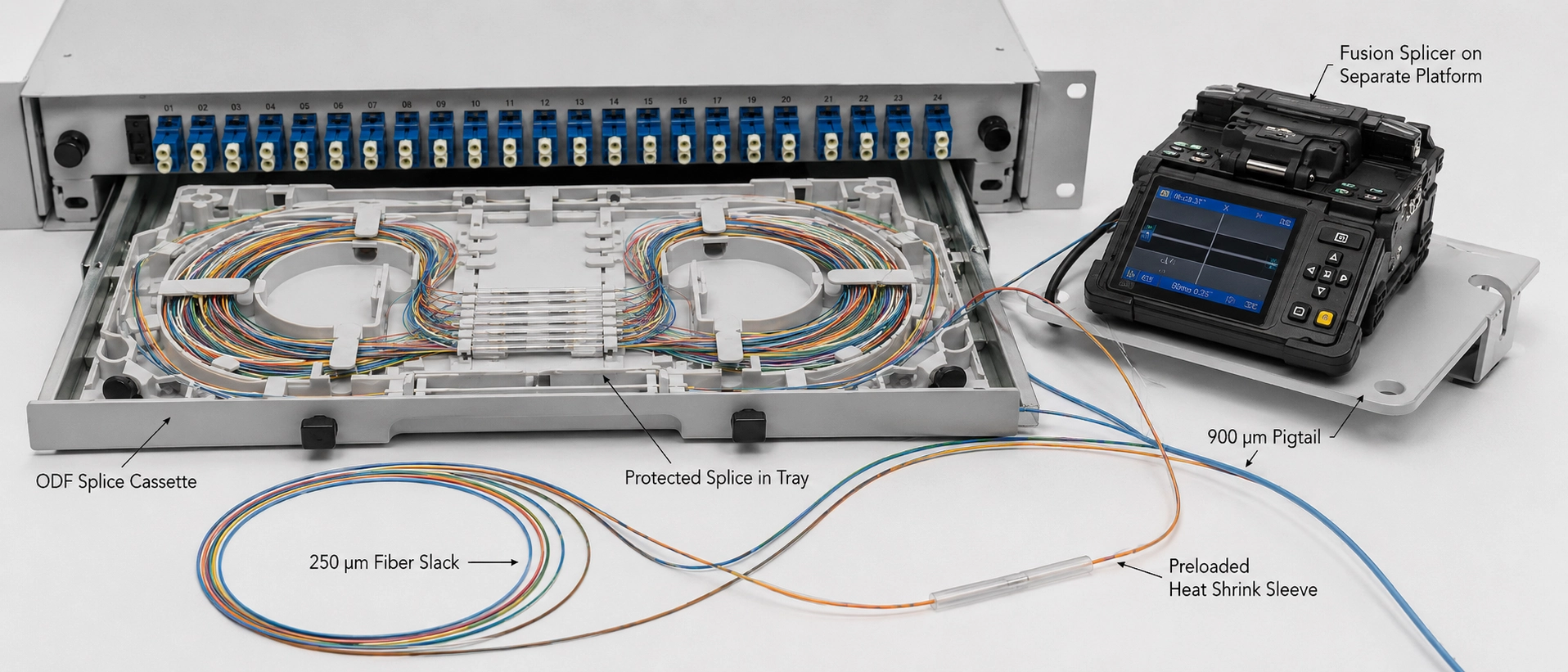
Ribbon and Mass-fusion Architecture
Mass-fusion systems are designed to move multiple fibers through the workflow together. Individual 900µm buffers can work against that density advantage.
Our position is more specific than the common "900µm indoors, 250µm outdoors" rule: choose the presentation used by the splice architecture, not the building boundary.
The Best Assembly May Use Both Sizes
A 250um vs 900um fiber pigtail assembly does not need the same protection diameter from the connector to the splice. This is the article's mid-content exact-match anchor, but it also describes an important physical design option.
A hybrid cassette can route 900µm buffered fiber from the connector or adapter panel through the area where technicians handle individual pigtails, then transition at a defined protected point inside the cassette to 250µm coated fiber for the splice and slack-storage region. The splice-side section gains routing density without forcing the connector-side section to give up handling protection.
This is useful when one blanket diameter specification is being asked to solve two different mechanical requirements. The termination side needs handling protection, while the splice side may need routing density.
For procurement, therefore, "250 or 900µm?" is sometimes incomplete. The drawing should identify where each fiber presentation starts and ends and whether the transition remains protected by the cassette.
The Installation Problems That Usually Appear After Procurement
A technically compatible fiber specification can still create unnecessary field work if stripping behavior, splice protection, and tray geometry are checked only after material arrives.
Stripability Is Part of the Specification
Two fibers sold as 900µm can behave differently during preparation because nominal outside diameter does not tell you how strongly the buffer is bonded to the underlying coated fiber.
When a tightly held buffer cannot be removed cleanly over the required preparation length, technicians should not compensate with a harder single pull. Shorter stripping segments reduce the load applied to exposed fiber. If preparation is still inconsistent, the stripping tool and buffer construction should be reviewed before production installation.
For a 900um fiber pigtail supplier RFQ, "900µm" alone is therefore incomplete. Specify the buffer construction or preparation requirement and confirm that the intended stripping method is compatible with it.
Splice Protectors Must Fit the Tray Holder
The fusion splicer handles prepared glass, but the tray has to manage the protected splice afterward. Protector dimensions, sleeve holder, and routing path therefore form one mechanical system.
Check the splice holder's supported protector dimensions before ordering the sleeves. A protector that does not seat fully in the holder can push the fiber transition toward the tray wall and create an unnecessary bend immediately beside the protected splice.
This is more useful than assuming that a longer protector is automatically safer.
Check the Tray With the Cover Closed
A routing arrangement that fits while the cassette is open is not necessarily a finished installation.
After the splices, protectors, and slack have been stored, verify that closing the cover does not compress loops, lift fibers from retainers, or create a sharp transition beside a protector. This is where buffer selection stops being a catalog comparison and becomes an enclosure-design decision.
What We Would Put on a Fiber Pigtail RFQ
For a custom fiber pigtail assembly, specifying only "250µm" or "900µm" leaves several variables unresolved. Two quotations can match the nominal diameter while differing in fiber type, strip behavior, connector construction, identification, and how the assembly actually fits the intended tray.
A production RFQ should define:
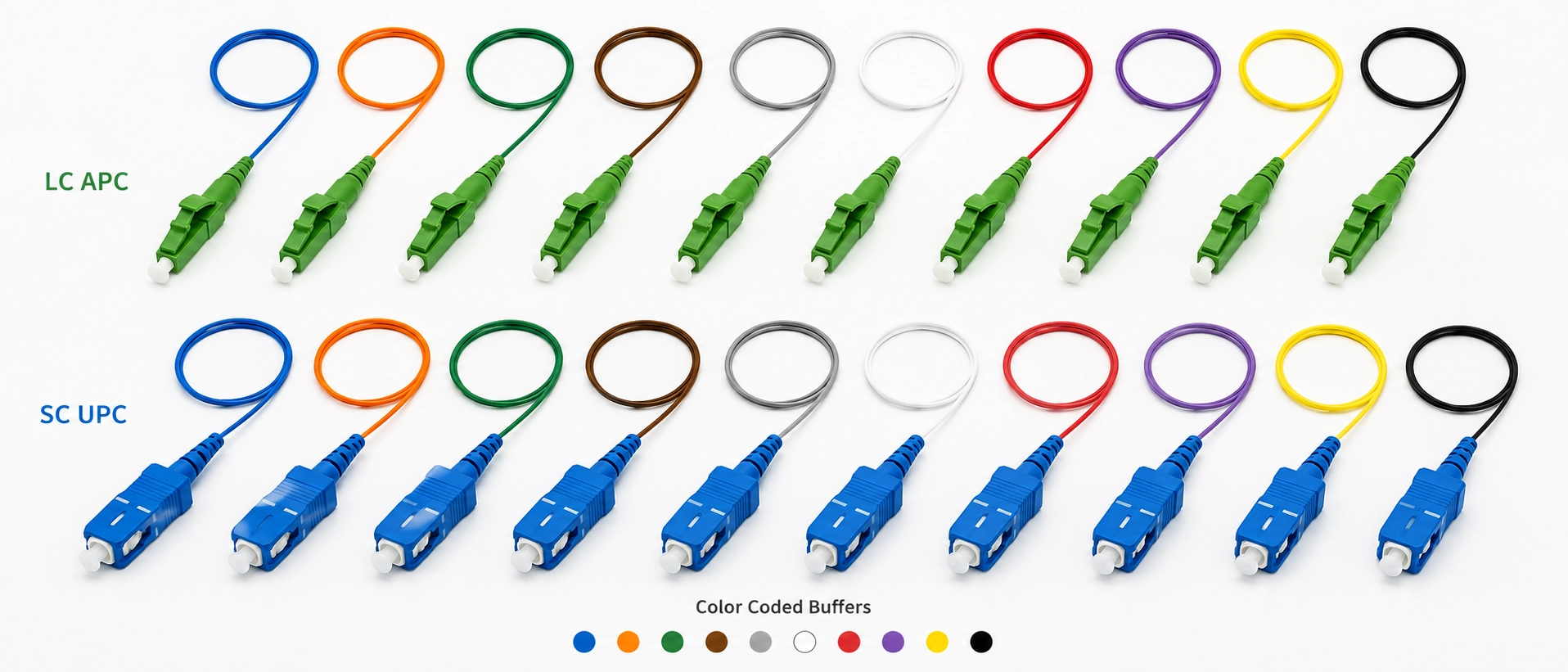
- Optical fiber type, such as OS2/G.652.D, G.657.A1/A2, OM3, or OM4.
- Fiber presentation: 250µm coated fiber, 900µm buffered fiber, or a defined transition between them.
- Connector type, such as LC, SC, or FC.
- Polish type, UPC or APC where applicable.
- Fiber count and identification/color sequence. When identification must match the cable plant, define the convention explicitly. Our fiber optic color code guide covers this layer.
- Pigtail length and required tolerance.
- Optical acceptance criteria for the finished connectorized assembly.
- Installation environment and enclosure type, such as ODF, splice cassette, FTTH termination box, or an outside-plant closure interface.
Those fields prevent specification ambiguity, but they still cannot prove that the assembly will physically route through a particular enclosure.
For a fiber pigtail for telecom installation, adding the tray drawing or a clear routing photo to the RFQ gives the supplier information that a text specification cannot provide: connector exit direction, buffer transition location, sleeve-holder geometry, and the available path for storing slack.
Choose by Deployment Architecture, Not by Habit
| Deployment situation | Starting choice | Engineering reason |
|---|---|---|
| 250µm OSP trunk into a normal ODF | 900µm pigtail | Easier individual handling; 250µm-to-900µm splicing is normal |
| Low-count FTTH box with adequate routing room | Usually 900µm | Maximum density is rarely the controlling constraint |
| Compact high-density cassette | Evaluate 250µm first | Reduces routing bulk inside protected space |
| Ribbon or mass-fusion layout | 250µm/ribbon architecture | Preserves the density advantage of the splice method |
| Fiber repeatedly handled outside a protected tray | Neither should be the default | Use appropriately jacketed or mechanically protected cordage |
The most useful signal that the 900µm default has broken down is not an arbitrary fiber-count threshold. It is a routing conflict. If the planned 900µm sections prevent the required slack, protector placement, or cover clearance from coexisting inside the tray, evaluate the 250µm architecture.
Before releasing a high-count 250um vs 900um fiber pigtail specification, compare it with the real tray drawing. Connector exit, sleeve-holder position, buffer transition, and stored slack need to work simultaneously after the cover closes.
If the installation actually requires jacketed cordage rather than pigtail routing, FB-LINK's fiber optic patch cable configurations cover the relevant connector, fiber, and protection options.
FAQ
What is the main difference between a 250µm and 900µm fiber pigtail?
A 900µm pigtail adds a protective buffer around the approximately 250µm coated fiber, so the practical differences are handling, mechanical protection, stripping, and tray density rather than optical performance.
Can I fusion splice 250µm fiber to a 900µm pigtail?
Yes. If the underlying optical fibers are compatible, the protective layers are removed from the splice area before the prepared glass fibers are fused.
Does a 900µm pigtail have lower insertion loss?
No. Buffer diameter itself does not reduce insertion loss; optical performance depends on fiber compatibility, splice quality, connector quality, and the rest of the optical path.
Which buffer size is better for a high-density splice cassette?
A 250µm fiber pigtail is usually the better starting point when protected routing space is the primary constraint, while 900µm is practical when handling matters more and sufficient tray space is available.
Which buffer size should I use in a standard ODF?
A 900µm pigtail is usually the practical default for a standard ODF with adequate routing space and individual fusion splicing.
Before You Freeze the Pigtail Specification
Buffer size should be decided before the pigtail becomes a fixed purchase-order line item. By that stage, the tray, sleeve holder, stripping workflow, and routing path may already have determined which presentation is practical.
For an actual 250um vs 900um fiber pigtail project, give FB-LINK the connector and polish, optical fiber specification, required fiber presentation, fiber count, pigtail length, and tray or enclosure drawing. Those inputs allow the proposed construction to be reviewed against the splice-side and termination-side requirements before the specification is frozen.
If project-specific pigtail test documentation, stripping behavior, or assembly tolerances are required, state them explicitly in the RFQ and ask for confirmation against the exact proposed pigtail construction. Do not assume a test claim published for another fiber assembly automatically applies to the pigtail being purchased.