An SC/APC connector must not be directly mated to an SC/UPC connector. Around a 1×2 PLC splitter, check the input, both outputs and the test connections before accepting the installation. A mismatch can produce excessive loss and reflection and may damage the mating end faces. A connection that passes light is not sufficient evidence of correct matching. (EXFO)
For the field team, the task is to identify each actual mating pair, correct any uncertainty in the connections, and record optical results against the approved project requirements. The checks below keep those decisions separate from assumptions about connector color or catalog performance.
Identify Every Mating Interface Before You Connect
Start with the splitter drawing and the installed port map. Assign an identity to IN, OUT1 and OUT2, then trace the connector that will physically mate with each one. If the assembly uses a bulkhead adapter, include the connector behind the panel in that check.
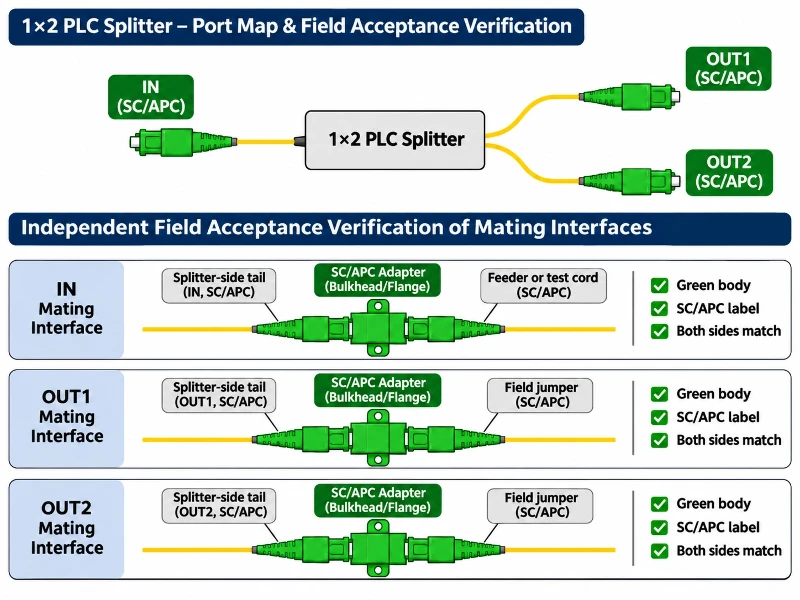
Use a separate row for every splitter leg:
| Splitter leg | Assembly connector and polish | Actual mating connector and polish | Confirmation evidence | Connection status |
|---|---|---|---|---|
| IN | Record from the supplied assembly | Record the feeder or test-cord end | Drawing revision, marking and photo | Confirmed or hold |
| OUT1 | Record independently | Record the first branch or test-cord end | Port identity and interface documentation | Confirmed or hold |
| OUT2 | Record independently | Record the second branch or test-cord end | Port identity and interface documentation | Confirmed or hold |
These are proposed record fields, not a completed inspection. Do not fill all three rows from the product title alone. The delivered assembly and the approved drawing must agree, including any intentionally different end configurations. Leave an unidentified interface on hold until its requirement is confirmed.
For background on the component inside the assembly, see how a PLC splitter works. The field record should still identify the external connections individually.
Why an 8° APC End Face Cannot Mate with UPC
UPC uses a slightly convex end face; APC uses an angled physical-contact polish, commonly 8°. That angle describes the end-face geometry relative to a plane perpendicular to the fiber axis. It does not mean that the fiber bends inside the connector or that the adapter sleeve is tilted by 8°. The angle reduces light reflected back into the guided path. (Fluke Networks)
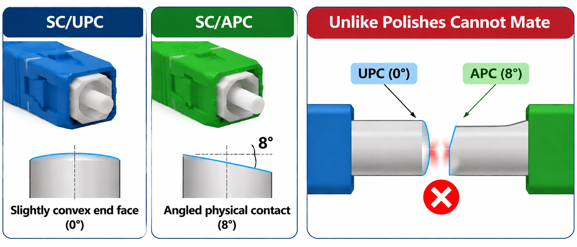
When APC and UPC ends are brought together, their contact geometries are incompatible. The SC housing fitting into an adapter does not establish a correct optical connection. Do not deliberately mate unlike polishes to see whether the link works; Fluke warns that doing so can damage the end faces. Damage is a risk, not proof that every accidental connection has crushed the fiber. (Fluke Networks)
Separate Connector Return Loss from Splitter and Link Results
Before judging a result, name the object being measured and the reference planes. A connector result, a splitter assembly result and a complete optical distribution network result answer different questions.
| Measurement object | Reference boundary to record | Conditions to document | Source of the acceptance limit | Result entry |
|---|---|---|---|---|
| A connector interface | The specified mating interface and reference connection | Wavelength and connector test method | Applicable connector specification and project requirement | Value, unit and comparison |
| The splitter assembly | Identified port and assembly boundaries | Wavelength, other-port treatment and whether connectors are included | Approved assembly specification and test method | Port, value and comparison |
| An installed link or ODN section | Defined near and far boundaries | Direction, wavelength, included components and method | Approved link acceptance plan | Section, value and comparison |
This table is a planning aid. It does not prescribe a test method or acceptance value. Keep transmission loss and returned-light measurements separate: an insertion-loss or received-power result alone does not establish reflection performance.
FOA distinguishes a connection's reflectance from the aggregate return measured over a fiber section, which can include distributed backscatter. A localized event value and link ORL must therefore retain their measurement boundaries. (FOA)
What a 50 dB or 60 dB Figure Actually Describes
Use positive return loss and negative reflectance consistently. For the same measurement boundary and incident-power reference:
A return loss of 50 dB corresponds to reflectance of −50 dB. At 60 dB RL, the returned-power fraction is 10⁻⁶ rather than 10⁻⁵: one tenth as much under the same reference conditions. This is a calculation illustrating the definition, not an Evolux test result or a tenfold improvement in transmission performance. (FOA)
An APC label does not set a universal 60 dB splitter threshold. For example, CommScope lists SC/APC input and output interfaces on its 1×16 model 760263891, but specifies minimum splitter return loss of 50 dB. This is a manufacturer-published specification checked on November 13, 2026; the page does not give a complete return-loss test method alongside that value. It is an example of the measurement distinction, not a comparison test or a specification for an Evolux 1×2 unit. Use the exact assembly specification and agreed conditions for the unit under test. (CommScope)
Check Colors, Labels and Both Sides of the Adapter
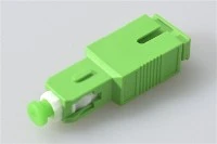
Green commonly identifies single-mode APC connectivity, while blue commonly identifies UPC. Treat those colors as an initial clue. EXFO notes that the actual connector inside an instrument port may require confirmation from additional markings or interface details. (EXFO)
For each panel connection, compare the front jumper, the adapter identification and the rear pigtail with the port documentation. Resolve conflicting labels before mating. A green front face cannot verify an unseen connector behind it.
An ordinary mating adapter aligns compatible connectors; it cannot make an APC end face compatible with a UPC end face. FOA's guidance on mismatched test interfaces calls for a cable with the correct termination at each end, rather than an adapter that brings unlike polishes together. (FOA)
Color coding and labels support identification; they do not provide a mechanical guarantee against misconnection.
Match Test Cords and Inspection Tips to Each Port
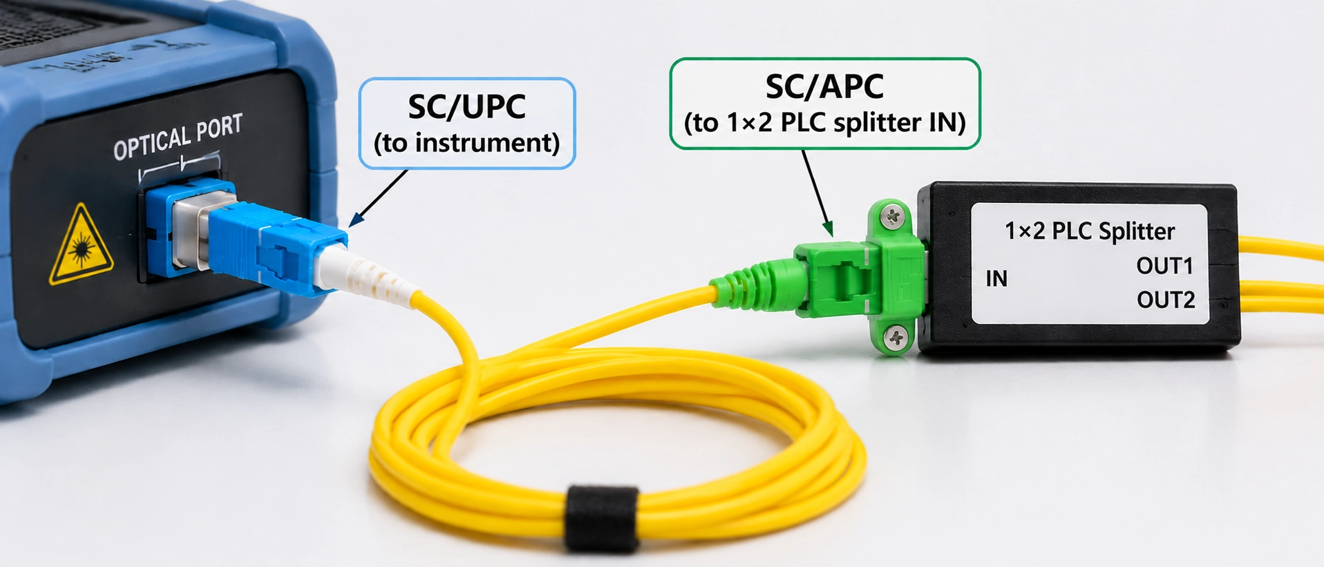
Check the test setup as carefully as the installed assembly. For physical-contact ports, each test-cord end must match the interface it touches. A cord can have APC at one end and UPC at the other without creating a mismatched mating pair.
| Confirmed physical-contact interfaces | Cord end at the instrument | Cord end at the assembly |
|---|---|---|
| SC/APC instrument and SC/APC assembly | SC/APC | SC/APC |
| SC/UPC instrument and SC/APC assembly | SC/UPC | SC/APC |
| SC/APC instrument and SC/UPC assembly | SC/APC | SC/UPC |
These examples describe interface matching only. For an OTDR, the launch and receive arrangement must also satisfy the instrument's requirements for resolving the events being measured. FOA describes using a hybrid launch cable with each end matched to its respective port. An ordinary short jumper is not automatically a suitable launch cable. (FOA)
Check the instrument manual before applying the table to a power-meter input. Some detector ports use non-contact arrangements that accept more than one polish type; that exception does not apply automatically to an OTDR port or a light-source output. (Fluke Networks)
Also fit the inspection tip specified for the connector. VIAVI states that an APC inspection tip is needed for APC fiber; a tip mismatch can leave the image only partly focused. Confirm the tool setup before interpreting a blurred image as damage. (VIAVI Solutions)
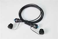
When specifying fiber optic patch cords with specified end interfaces, record end A and end B separately. Confirm any additional test-cord requirements with the instrument documentation; a standard patch-cord listing does not establish test suitability.
Inspect, Correct and Retest a Suspected Mismatch
Use the following as a suggested troubleshooting sequence alongside the approved project procedure:
-
Hold the affected connection. Record its identity and avoid repeated mating while the polish remains uncertain. Arrange any required service isolation before disconnecting.
-
Confirm both interfaces. Compare actual markings, the assembly drawing and the instrument requirements. Correct a mismatched test cord before judging the installed splitter.
-
Inspect both mating end faces. Use the appropriate video inspection probe under the site's optical safety procedure. Retain images tied to the two connector identities.
-
Treat contamination or suspected damage separately. Clean contamination with the approved method and reinspect. If a defect remains, refer it for assessment or replacement under the applicable procedure; changing the jumper color does not resolve damage.
-
Restore the approved configuration and retest. Record changed components, test settings and the reference setup. Establish the reference again when the prescribed method requires it, and retain the new results alongside the original files.
IEC 61300-3-35:2022 covers inspection of debris, scratches and defects. Its public summary explicitly states that visual inspection supplements, rather than replaces, attenuation and return-loss measurements. A clean-looking image therefore cannot complete optical acceptance by itself. This guide does not reproduce the standard's detailed defect criteria. (IEC)
If loss remains excessive after the interfaces and test setup are confirmed, continue the fault investigation. A loss value alone does not identify a mismatch; retain evidence before attributing the problem to the splitter chip or replacing an entire batch.
Record the Evidence Required for Field Acceptance
The handover should connect each result to the component, interface and test configuration that produced it. The following fields are a proposed record structure, not an operator-approved acceptance form.
| Record group | Fields to retain | Review purpose |
|---|---|---|
| Asset identity | Project, cabinet or box location, model, batch or serial identity, IN/OUT1/OUT2 map | Connect the evidence to the installed assembly |
| Mating interfaces | Connector family and polish at both ends of every mating pair, document revision and identification photos | Show how interface compatibility was established |
| End-face inspection | Probe and tip, images of both ends, cleaning or corrective action and reinspection result | Preserve the basis for the inspection decision |
| Test configuration | Measurement object, reference planes, direction, wavelength, instrument identity, calibration status, cord identities, reference method and other-port state where required | Make the measurement configuration traceable |
| Optical results | Each required loss or reflection item, applicable limit and its source, measured value, result and original file | Support acceptance using the specified criteria |
| Correction and release | Replaced or reterminated components, retest references, record owner, authorized acceptance reviewer and date | Show what changed and who approved release |
For branch measurements, keep IN-to-OUT1 and IN-to-OUT2 results identifiable; do not use one passing branch as the record for both. Add reverse-direction tests only where the approved method calls for them. Likewise, record the actual required treatment of unused ports rather than assuming a dust cap defines their optical termination.
Before release, resolve missing port identities, unexplained changes in setup and results without a cited acceptance limit. If the project has no agreed criterion for a required measurement, obtain that criterion from the responsible project authority before assigning pass or fail.
Specify a Matched 1×2 SC/APC Splitter Assembly
If the investigation identifies a need for replacement or additional assemblies, convert the completed port map into the supply specification. For a configuration requiring SC/APC on all three splitter legs, state that requirement separately for IN, OUT1 and OUT2.
Include the fiber specification, package and pigtail requirements, mating interfaces, label text, quantities and required optical report fields. For package and identification options to discuss with the supplier, consult the PLC splitter configurations, then request confirmation for the exact assembly. State the measurement wavelengths, limits and whether connector contributions are included. Keep any requirements for test cords separate from those for installed patch cords.
Evolux lists a 1×2 SC/APC PLC splitter mini module. The listing does not by itself confirm the connector on each leg of the assembly to be supplied or its acceptance results. Send the three-port map, mating-interface photos and acceptance requirements with your inquiry so the configuration and available supporting documents can be confirmed before ordering. Request a confirmed IN/OUT1/OUT2 interface drawing and the applicable specification and test-report details for the quoted configuration.
Where the requirement includes project-specific identification or matched components, include those details in the same inquiry using the OEM/ODM specification process. Availability and performance requirements need confirmation for the quoted assembly. Labels help the field team identify the intended connections; the acceptance record must still show that they were checked and tested.