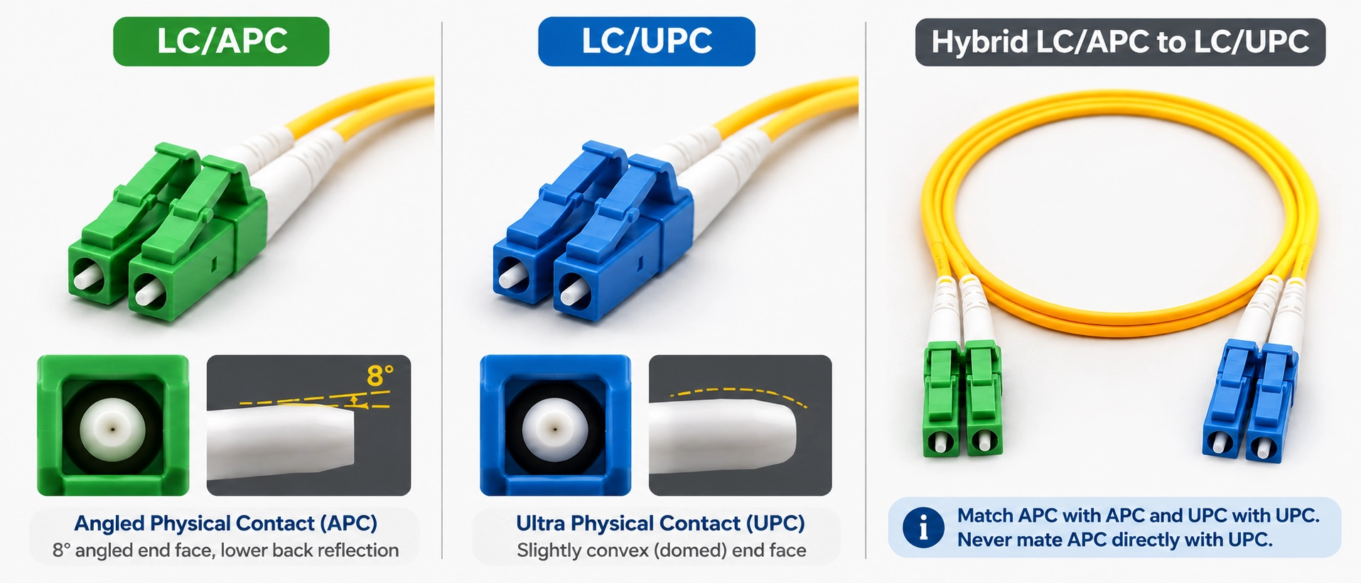
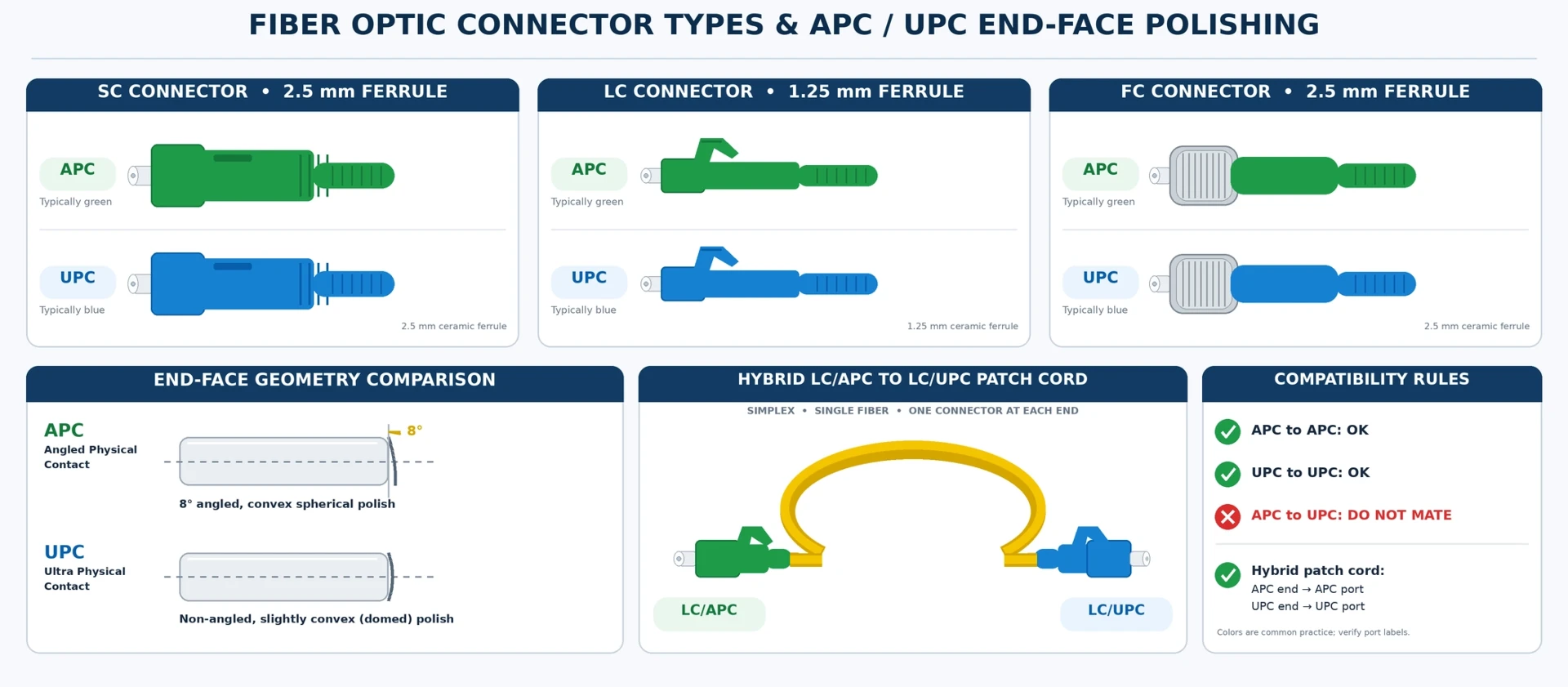
An LC APC to LC UPC patch cord can connect an LC/APC interface to an LC/UPC interface when each cable end matches the interface it contacts and the rest of the optical link is compatible. It does not make APC and UPC connector faces suitable for direct mating. The practical rule is to check the polish at every physical contact, rather than requiring both ends of a continuous fiber to have the same polish. Fluke Networks documents a test arrangement for mixed LC/APC–LC/UPC singlemode links. (Fluke Networks)
What an LC APC to LC UPC Patch Cord Can Connect
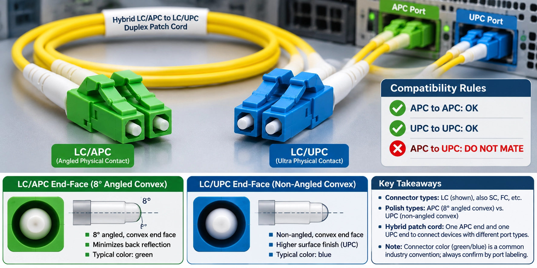
A hybrid-polish patch cord has an LC/APC connector at one end and an LC/UPC connector at the other. The fiber between those ends carries the light; there is no direct APC-to-UPC end-face contact inside that continuous fiber. This distinction explains why a cable with different end polishes can serve a link whose individual mating points still use matching polishes.
Consider this illustrative connection example, rather than a verified customer installation:
| Location | Interface presented by the installation | Patch-cord end | Connection decision |
|---|---|---|---|
| End A | Documented LC/APC interface | LC/APC | Matching-polish candidate; confirm the remaining interface requirements |
| End B | Documented LC/UPC interface | LC/UPC | Matching-polish candidate; confirm the remaining interface requirements |
| Either end | APC connector face directly contacting a UPC face | Mismatched polish | Do not use this arrangement |
This example assumes compatible optical equipment and fiber. A passive patch cord does not change wavelength, convert a network protocol, or make incompatible transmitters and receivers work together. Successful port matching is one part of link design, not proof that the complete system will operate.
Check Each Mating Point Before Choosing the Cable
Confirm the Port Specification
Start with the equipment manual, port designation and exact part number. For a patch panel, identify the termination behind the adapter as well as the front access point. An adapter opening alone does not establish the polish of the connector behind it.
Record the connector family and polish separately: "LC" describes the interface family, while "APC" or "UPC" identifies the end-face finish. A familiar equipment label such as SFP, OLT or PON is not a substitute for a port specification. If the required finish is unclear, obtain the equipment supplier's confirmation before ordering or connecting a cable.
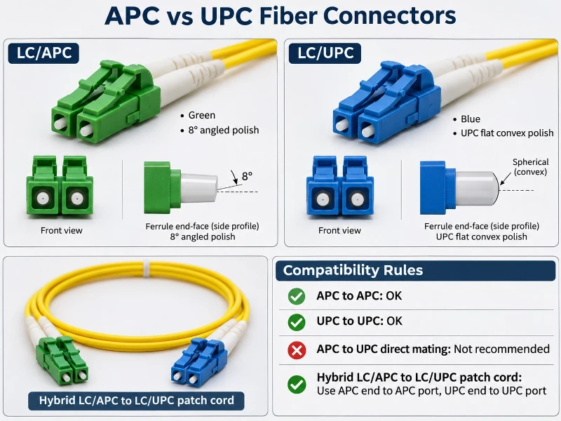
Green and blue housings can help identify likely APC and UPC ends, but use the product identification and approved documentation to make the decision. Do not classify an unmarked cable solely by its color.
Match the Polish at Every Physical Contact
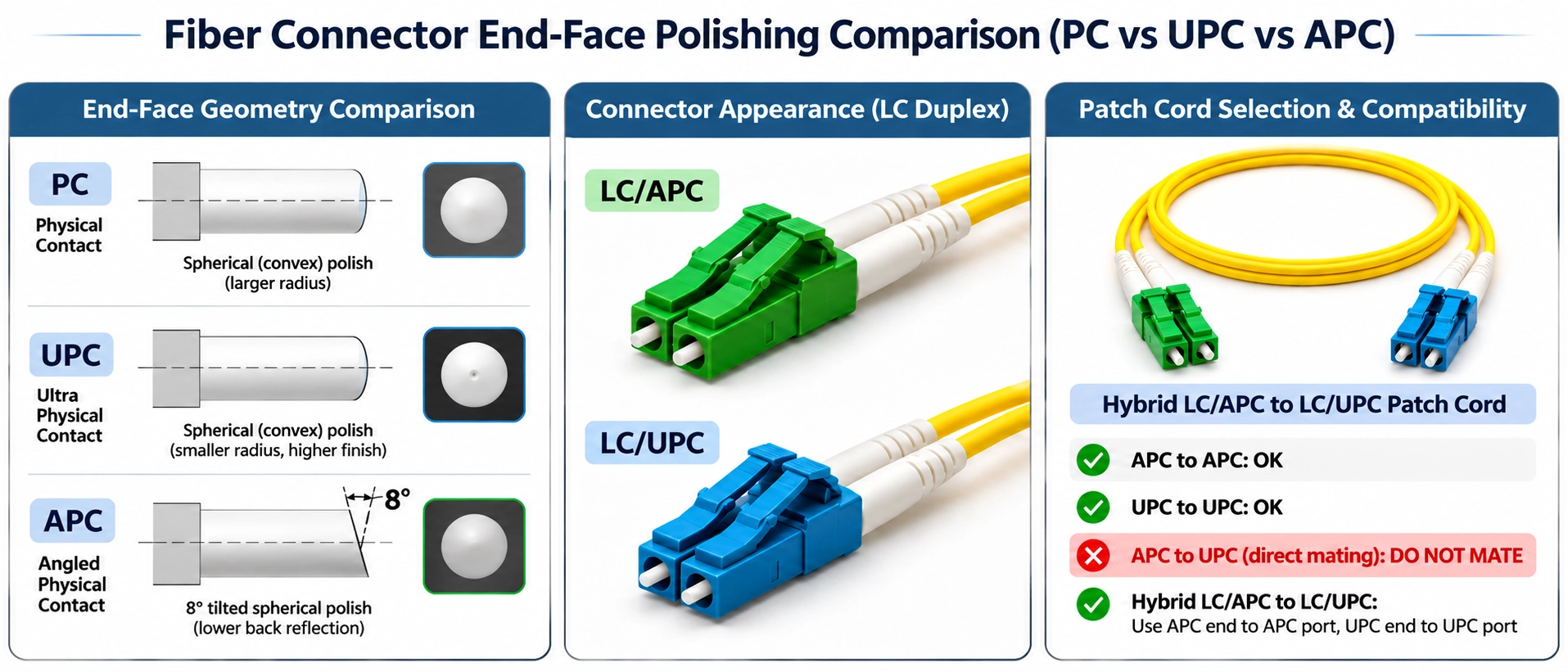
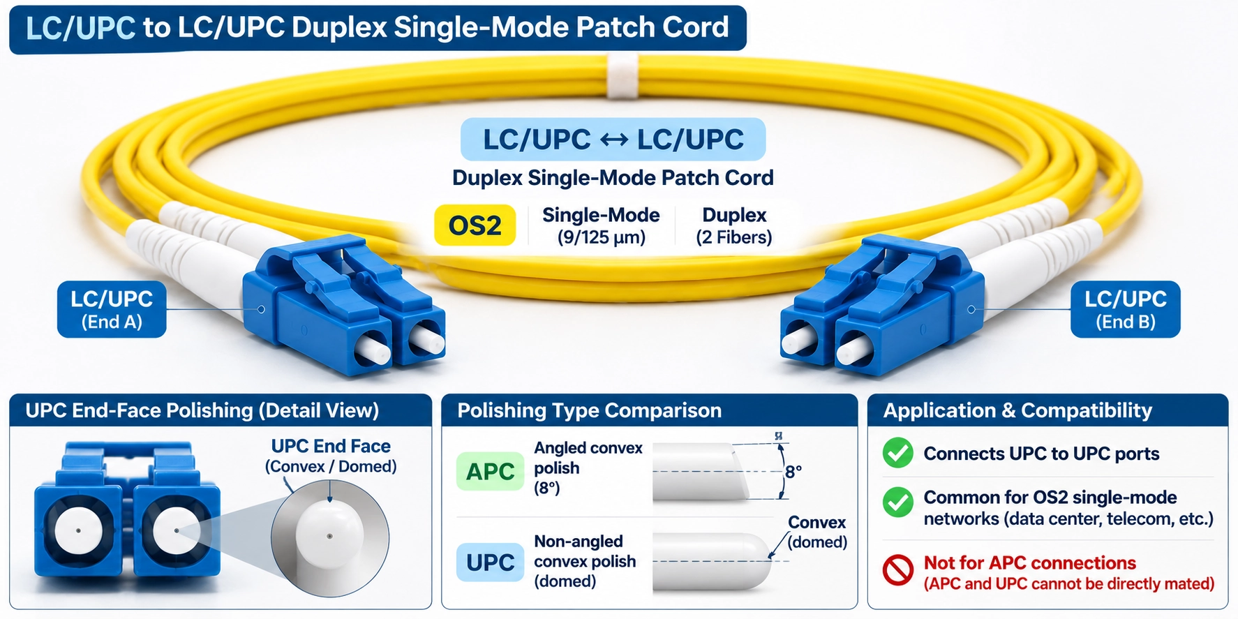
UPC uses a slightly curved contact face, whereas APC introduces an angle. Directly mating the two creates an unsuitable contact geometry and can impair performance or damage an end face. Fluke's explanation treats this as a mating restriction; it does not prohibit a continuous fiber from having different polishes at its opposite ends. (Fluke Networks)
Apply the rule to intermediate couplers, extension cords and test leads as well as the two equipment ports. A correctly specified hybrid cable can still be installed incorrectly if an additional lead introduces an APC/UPC contact elsewhere.
Hybrid Patch Cord, Coupler, or Conversion Adapter?
The word "adapter" is used for products with different functions. Before selecting one, identify what its external interfaces accept and what it actually does between them.
| Option | What to establish | Main limitation |
|---|---|---|
| Hybrid-polish patch cord | APC at the documented APC interface and UPC at the documented UPC interface | Still requires suitable fiber, routing, channel mapping and optical performance |
| Ordinary alignment-sleeve coupler | Compatible connector arrangement and matching polish on the faces it brings together | Aligns connectors; does not repolish or reshape their faces |
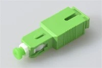
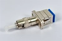
| Purpose-built conversion adapter | Explicit APC and UPC external interfaces, approved usage and documented optical specifications | The product name alone does not establish its internal design, loss or suitability |
A standard coupler should not be treated as a device that makes direct APC/UPC contact acceptable. For a purpose-built converter, obtain its own data sheet and verify each external connection. Allow for its specified optical contribution and mechanical projection at the port; do not assume it adds no loss.
If there is enough routing space, a hybrid cord gives the installer two clearly identified ends to match. If space favors a compact converter, assess that particular component against the installation requirements. This is an engineering choice based on documented interfaces, rather than a rule that every product called an adapter is equivalent.
Specify Fiber Count, Fiber Type, and Channel Mapping
Simplex or Duplex
Choose the number of fibers from the equipment's optical path requirements. Simplex describes a one-fiber cable configuration; duplex describes a two-fiber configuration. Those descriptions do not, by themselves, establish the communication direction: a system designed for bidirectional transmission can use one fiber.
Different polishes at the cable ends do not determine fiber count. If a system requires separate transmit and receive fibers, confirm the appropriate duplex arrangement. If it uses a single-fiber optical interface, confirm that requirement and the associated equipment compatibility instead.
Specify the actual singlemode fiber requirement from the system design. Do not infer a fiber category, bend performance or operating distance from the LC connector name. Use the approved cable data sheet to confirm bend limits, jacket suitability and installation conditions.
Record Both Ends and the Channel Path
For a duplex assembly, document the correspondence between individual fibers. Polishing does not automatically set polarity or exchange transmit and receive channels.
Use an end schedule such as the following illustrative mapping. The labels are project identifiers, not a universal polarity convention.
| Project fiber ID | End A connector and polish | End B connector and polish | Required path |
|---|---|---|---|
| Fiber 1 | LC/APC | LC/UPC | A channel 1 to the B channel required by the equipment design |
| Fiber 2 | LC/APC | LC/UPC | A channel 2 to the other required B channel |
Add the equipment port labels, duplex-clip orientation and viewing direction to the drawing when they affect installation. Verify continuity against that drawing before acceptance. A purchasing description that says only "duplex APC to UPC" leaves the channel path unresolved.
Read Insertion Loss and Return Loss as Separate Requirements
Insertion loss concerns transmitted power lost through the defined test object. Return loss concerns light returning toward the source. Passing a transmission-loss check does not establish that a reflection requirement has also been met.
Specify Each End
For a mixed-polish assembly, identify which end and mating arrangement a result describes. A single headline return-loss figure can obscure different requirements at the APC and UPC ends.
The following is a requirements template, not an EVOLUX performance specification:
| Record field | Information to agree before acceptance |
|---|---|
| Test object | Individual termination/mated connection, finished assembly, or installed link |
| Identification | Cable ID, fiber ID, end designation and test direction |
| Insertion-loss requirement | Applicable maximum, units, wavelength and reference procedure |
| APC-end reflection requirement | Applicable RL minimum or reflectance maximum, with mating/reference conditions |
| UPC-end reflection requirement | Separately specified requirement and mating/reference conditions |
| Test conditions | Instrument, reference connectors, method, date and relevant environment |
| Scope of each result | Identify whether a reflection result applies to one mating point or the complete assembly/link; report each required test direction |
| Result record | Actual readings, pass/fail criteria and traceable report identification |
Ask whether a quoted value is typical or an acceptance limit, and whether the reported loss includes one mating pair, both ends or a longer link. Those distinctions determine whether two reports are comparable. Agree the acceptance limits for the specified assembly before ordering; do not infer a product guarantee from the connector polish alone.
Separate Connector Results from Link ORL
Reflectance and return loss express the same power relationship using opposite signs under the corresponding definitions. FOA illustrates this with −50 dB reflectance corresponding to +50 dB return loss. This is a mathematical example, not a guaranteed connector grade. For return loss, a larger positive value means less reflected power; for reflectance, a more negative value means less reflected power. (FOA)
Optical return loss measured over an installed link can include multiple reflecting events and fiber backscatter. It must not be substituted for the result of one connector mating. Keep the measurement boundary, wavelength and method attached to every reported value. The APC end's result alone cannot certify the entire mixed-polish link. (FOA)
Inspect and Verify the Connection Before Acceptance
Before microscope inspection, isolate the fiber from optical sources and use a suitable optical power meter to verify that no optical power is present. Do not look into a connector or fiber end to check whether it is active. Follow the inspection instrument's safety instructions. (FOA fiber optic safety guidance)
Inspect accessible end faces with suitable equipment before mating. If contamination is found, use the approved cleaning method and inspect again. A protective cap is not an inspection record. If damage or persistent contamination is visible, resolve it before proceeding with acceptance testing. FOA emphasizes the sensitivity of reflection measurements to cleanliness. (FOA)
Keep physical inspection, continuity verification and optical measurements as distinct checks. Each answers a different question: whether the contact surfaces are acceptable, whether the intended fibers connect, and whether the defined optical requirements are met.
Ordinary Patch Cords vs Test Reference Cords
A production patch cord does not become a test reference cord merely because its connectors fit. When testing requires reference-grade cords, identify the required cord type and verify the reference setup before measuring the installation.
Fluke's CertiFiber Pro procedure for mixed LC/APC–LC/UPC links includes reference setup, reference-cord verification and saved verification results. It applies to the documented instrument and installed-link method. Its example settings or thresholds should not be copied into a factory patch-cord specification without establishing their applicability. (Fluke Networks)
For acceptance, retain the reference-verification record with the cable or link results. If reference quality is unknown, investigate that uncertainty before interpreting an unusually favorable loss reading as evidence of superior cable performance.
Document Instrument-Specific Exceptions
Some instrument inputs differ from ordinary physical-contact interfaces. Fluke explains that the CertiFiber Pro non-contact INPUT can accept APC or UPC, while its OUTPUT uses UPC. This is a model-specific input arrangement, not permission to mate APC and UPC connector faces elsewhere. Inspection accessories must also suit the connector geometry. (Fluke Networks)
Before using an exception, record the instrument model, exact port, adapter and applicable manufacturer instructions. Do not extend that exception to an unspecified power meter, transceiver or panel connection.
Final Specification Checklist for Your LC APC to LC UPC Link
A useful order description allows another person to reconstruct the connection and its acceptance requirements without guessing.
| Specification item | Detail to include |
|---|---|
| Equipment interfaces | End A and End B device/port identifiers and supporting documentation |
| Physical contacts | Connector family and matching polish at each mating point |
| Cable construction | Fiber count, fiber specification, length definition/tolerance, diameter and jacket requirements |
| Installation | Routing space, bend constraints, boot clearance and applicable environmental/fire requirements |
| Channel schedule | Individual fiber IDs, endpoint mapping and duplex orientation where relevant |
| Optical acceptance | Defined test object, wavelengths, IL requirements and reflection requirements for each applicable end |
| Verification records | Inspection/continuity records, test method, reference verification where required, results and cable IDs |
| Supply confirmation | Approved part number, confirmed configuration and agreed documentation |
For example, an order can identify a duplex singlemode assembly with LC/APC at End A and LC/UPC at End B, then attach the channel drawing and agreed test requirements. This is a description format, not confirmation that a particular length, jacket or performance grade is available.
For a simplex or duplex requirement, send EVOLUX your LC APC to LC UPC cable specifications, including the confirmed port details, fiber count, channel drawing and acceptance requirements. Request written confirmation of configuration availability, the applicable part number and the test documentation offered before ordering.