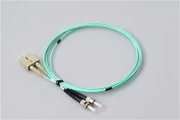
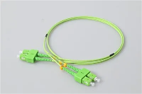
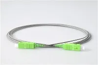
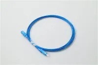
A polished ferrule can look clean and still be the wrong connector to mate. For pigtails, fiber connector inspection should answer four operational questions: Is the end face fit to use? Is the visible condition removable contamination? Does it need another inspection after cleaning? Or has the decision moved from cleanliness to optical qualification?
Inspect → identify the condition → clean only when cleaning can help → reinspect → mate or escalate to optical verification.
IEC 61300-3-35:2022 covers visual inspection requirements and quantitative end-face criteria. IEC TR 62627-01:2023 covers connector cleaning methods, tools, and procedures. Cleaning supports the inspection workflow, but it is not correct to describe the cleaning procedure itself as "IEC 61300-3-35 cleaning." (IEC 61300-3-35:2022; IEC TR 62627-01:2023)
A Clean-Looking Ferrule Can Still Be the Wrong Decision
The important distinction in fiber connector inspection before mating is not simply "clean versus dirty." It is removable condition versus permanent condition. Dust, loose debris, oily contamination, and some residues can respond to cleaning. A scratch, pit, chip, or polishing defect will not disappear because the technician repeats the same cleaning action.
IEC 61300-3-35:2022 evaluates debris, scratches, and defects and applies visual criteria to the optical interface. For cylindrical ferrules, the third edition also requires contamination inspection over the contact area extending to a diameter of up to 250 µm around the fiber. It removed the previous Zone C and D inspection requirements and moved the outer edge of Zone B from 115 µm to 110 µm. Those details matter because a narrow view centered only on the fiber can miss contamination elsewhere in the mating contact area. (IEC)
For a technician or QA engineer, this changes the acceptance question. Do not ask only, "Can I see a mark?" Ask, "What is the feature, where is it, can cleaning change it, and which acceptance requirement applies if it remains?"
IEC 61300-3-35:2022 Changed the Meaning of "Fail"
A connector cannot be rejected solely because it fails visual inspection.
IEC's third edition states that meeting the specified optical performance determines whether a connector can be used. The same standard states that visual inspection is additional to, and does not replace, attenuation, return-loss, or end-face parameter measurements. Those rules need to be read together. A visual failure is meaningful, but it is not automatically the final optical acceptance decision. (IEC)
That does not make visual criteria optional. Removable contamination remains an uncontrolled interface condition and should be addressed before mating or formal optical testing. For a permanent visible feature, proper cleaning first establishes that the feature is not loose contamination. After that point, the next decision depends on the applicable acceptance requirement, not on repeating the same cleaning cycle.
Connector cleanliness is also not a substitute for configuration verification. A physically clean pigtail can still be wrong for the port because connector body, polish, fiber mode, and interface requirements do not match. The separate fiber connector inspection before mating reference covers that compatibility decision.
How to Inspect a Fiber Optic Connector End Face Before Mating
A useful setup starts with the inspection system, not the cleaning tool. Video microscopes are preferable where direct optical viewing could create a laser-safety risk, and the fiber or port should be treated as potentially energized until the condition is verified.
For microscope selection, connector geometry matters. LC connectors use a 1.25 mm ferrule, while SC and FC connectors use a 2.5 mm ferrule, so the probe adapter or fixture has to match the interface. FOA also notes that 100× to 400× is a common magnification range for connector ferrule inspection. (FOA connector reference; FOA inspection reference)
An APC end face also needs the correct viewing arrangement. The objective is not maximum magnification for its own sake. The useful image is the one that keeps the fiber, relevant ferrule area, and defect location interpretable under the correct inspection profile.
For LC connector end face inspection, this is easy to get wrong. A highly magnified, sharply focused fiber image can still be incomplete evidence when the surrounding contact area is excluded from the field of view.
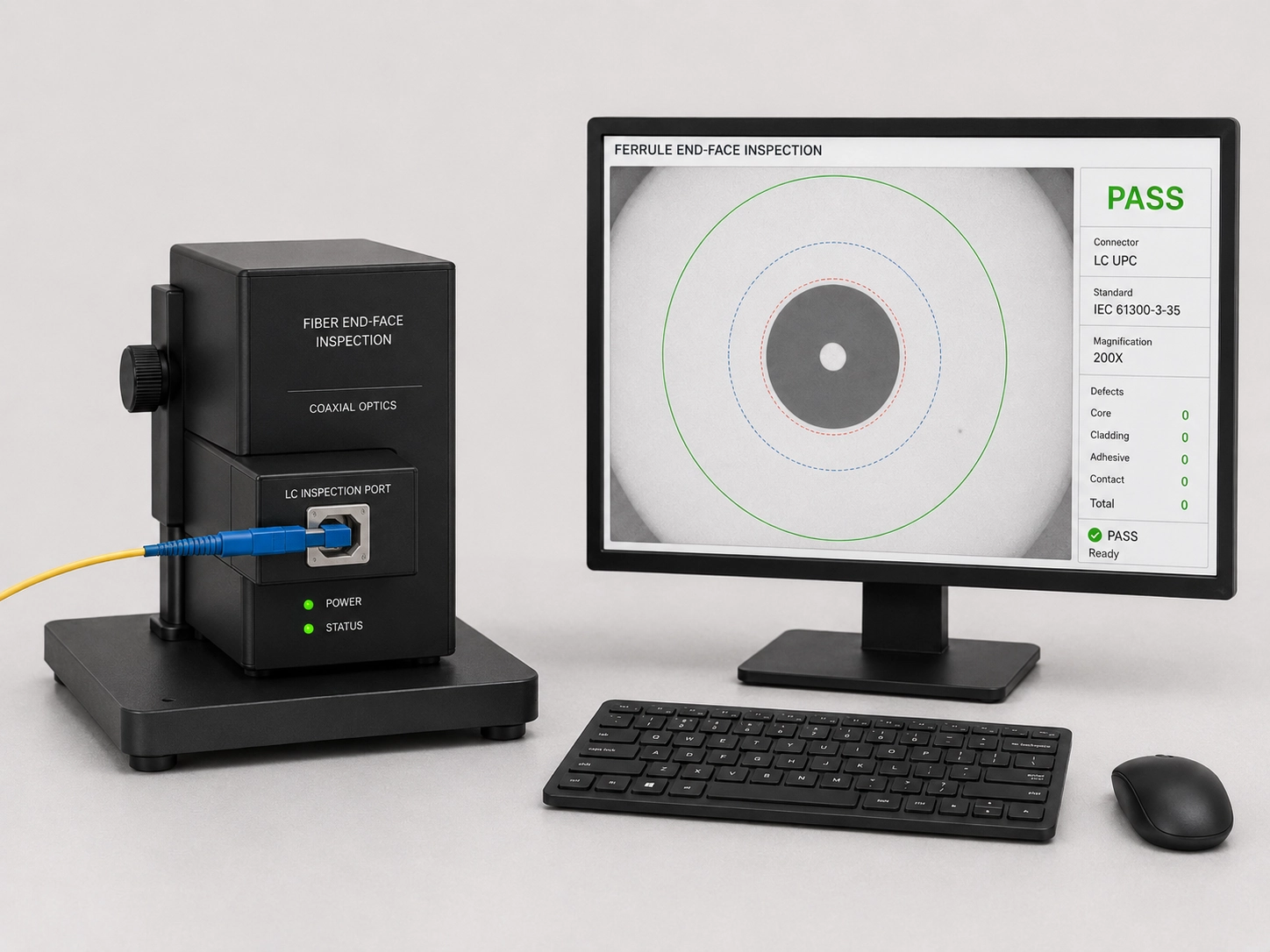
Read the End Face as a Failure Mode
The red FAIL result on an automated microscope does not tell you whether cleaning can fix the condition. Use the observed feature to choose the next action.
| Observed condition | Does cleaning normally change it? | Immediate action | If it remains |
|---|---|---|---|
| Loose particle / dust | Yes | Clean, then reinspect | Investigate the cleaning method or contamination source |
| Oil / film / residue | Often | Controlled wet-to-dry cleaning, then reinspect | Verify residue source and cleaning process |
| Scratch / pit / chip | No | Document; do not keep treating as dirt | Apply the relevant visual or optical acceptance requirement |
| Suspected geometry issue | No | Do not diagnose from a cleanliness image alone | Use the appropriate geometry or qualification measurement |
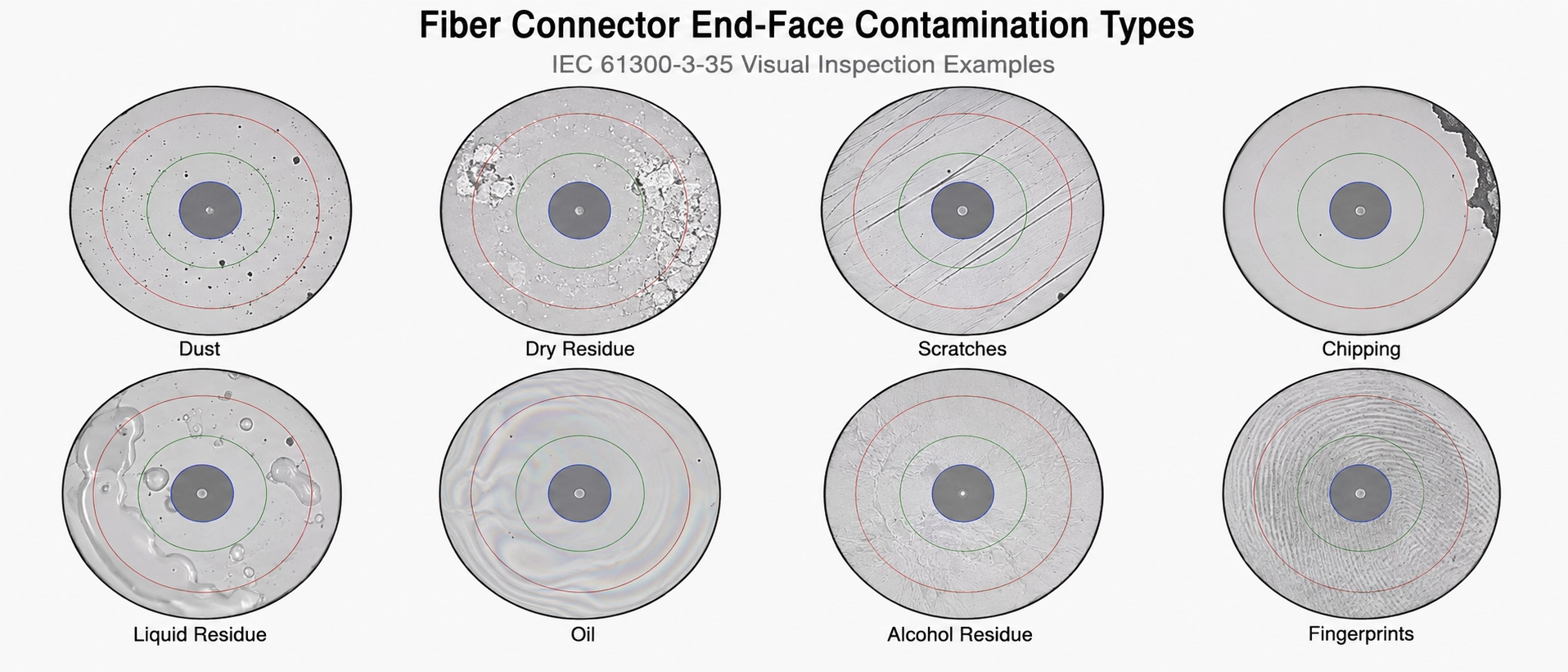
Automated inspection is a measurement system, not an infallible referee. IEC TR 63367:2021 summarizes a round-robin study of automated microscope systems and evaluates repeatability, reproducibility, and system-to-system variation in reported scratches. (IEC TR 63367:2021)
A production record therefore becomes more useful when it retains the image and the inspection context, not only a green PASS label. The record should identify the connector configuration and inspection profile and, where traceability matters, map the result to a lot or individual assembly.
A clean microscope image does not prove acceptable end-face geometry. Radius of curvature, fiber height or protrusion, and apex-related geometry belong to a different measurement problem. That distinction prevents a clean end face from being used as evidence for a characteristic the microscope did not actually measure.
Fiber Connector Inspection Procedure: Inspect, Clean, Reinspect
The inspection procedure should begin with the image, not with an automatic cleaning cycle. If inspection shows an acceptable end face and the mating side is also known to be clean, extra handling is not an improvement. If contamination is visible, cleaning has a defined reason.
IEC TR 62627-01:2023 details cleaning methods, typical tools and machines, and cleaning procedures; it explicitly points visual inspection back to IEC 61300-3-35. (IEC TR 62627-01:2023)
For routine fiber pigtail connector cleaning, use a fresh connector-appropriate cleaning surface or tool, then reinspect. When loose contamination disappears and the connector meets the applicable visual requirement, stop. Reusing the same contaminated section of a wipe or treating repeated rubbing as proof of diligence adds another uncontrolled handling event.
Where an oily film or stubborn residue remains, a controlled wet-to-dry method can be appropriate. The wet step loosens or dissolves contamination; the dry step removes the loosened material and cleaning-fluid residue. Do not leave a visibly wet interface to evaporate and assume that evaporation equals cleanliness. FOA describes wet/dry cleaning as generally preferred because the wet stage loosens contamination and the dry stage removes it. (FOA)
The inspection after cleaning closes the loop. A cleaning action without reinspection tells you what the technician did, not what condition the connector is now in.
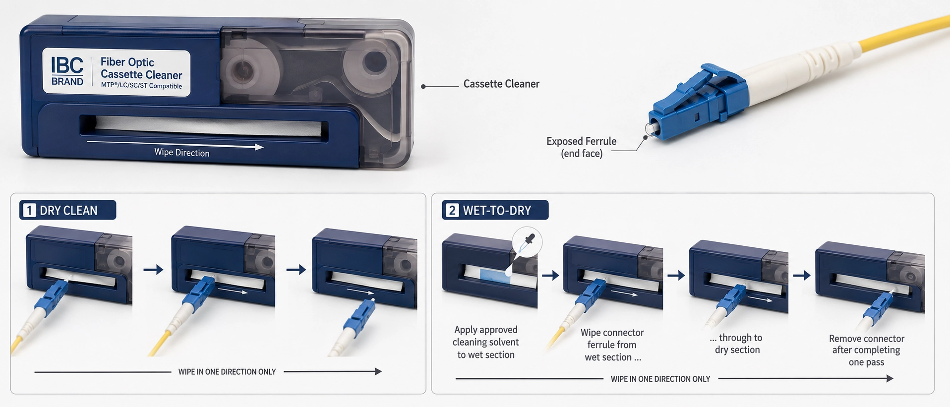
When Cleaning Stops Helping
Do not use repeated cleaning as a substitute for diagnosis.
If the same visible feature remains in the same position and with the same shape after a correctly executed cleaning cycle, change the working diagnosis. It may be a scratch, embedded particle, pit, chip, or polishing feature rather than removable debris.
When that persistent feature remains and the acceptance question is whether the connector satisfies the project's optical requirement, stop treating it as contamination and run the specified IL/RL or other optical qualification. Repeating the same cleaning action does not create stronger acceptance evidence.
This does not mean every visual fail can be ignored. Cleaning has a defined purpose: removing contamination. Once the observed evidence shows that purpose is no longer being served, the next test must address the actual acceptance question.
Four Sources of Recontamination That Are Easy to Miss
A protective cap reduces physical damage and additional environmental exposure, but it is not a cleanliness certificate. FOA documents that molded protective caps can carry dust or mold-release contamination and recommends inspection and cleaning after removal rather than assuming a capped connector remains clean. (FOA)
Dry cleaning solves many routine contamination problems, but rubbing can also generate static charge at the ferrule. That does not make dry cleaning wrong; it makes the subsequent reinspection important, particularly where airborne dust can be attracted back to a freshly handled interface.
Inspection hardware itself is repeatedly exposed to suspect connectors. If a probe fixture or adapter receives dirty ferrules throughout the day, it belongs inside the contamination-control process rather than outside it.
The same applies to reference cords, mating adapters, source outputs, and meter interfaces. A dirty test interface can contaminate a clean reference connector and alter subsequent measurements, so the test chain has to be treated as a connected contamination path.
For field work after splicing, this is where installation and test workflow meet. The fiber pigtail connector cleaning context should be completed before the newly spliced pigtail is treated as an accepted optical interface.
Factory, Field, and Troubleshooting Inspections Need Different Evidence
In factory QA, field commissioning, and troubleshooting, fiber connector inspection can follow the same basic inspection logic while requiring different evidence for acceptance.
| Scenario | Primary risk | Inspection emphasis | What happens after visual inspection | Required evidence |
|---|---|---|---|---|
| Factory-finished pigtail before packing | Process contamination, polishing defect, traceability gap | Repeatable image analysis under the correct profile | Pair with the optical tests required by the product specification | Image/result plus connector configuration and lot or ID mapping where required |
| Field installation before mating | Dust, fingerprints, cap contamination, dirty adapter | Inspect both mating interfaces and minimize unnecessary exposure | Mate promptly after acceptable inspection | Confirmation of both mating surfaces; post-splice test record when specified |
| Troubleshooting an installed link | Transferred contamination, persistent defect, misleading visual result | Inspect the connector, reference interface, and test setup as a system | Move to specified IL/RL or another diagnostic measurement when cleanliness no longer explains the result | Inspection image plus reference-interface condition and relevant optical measurements |
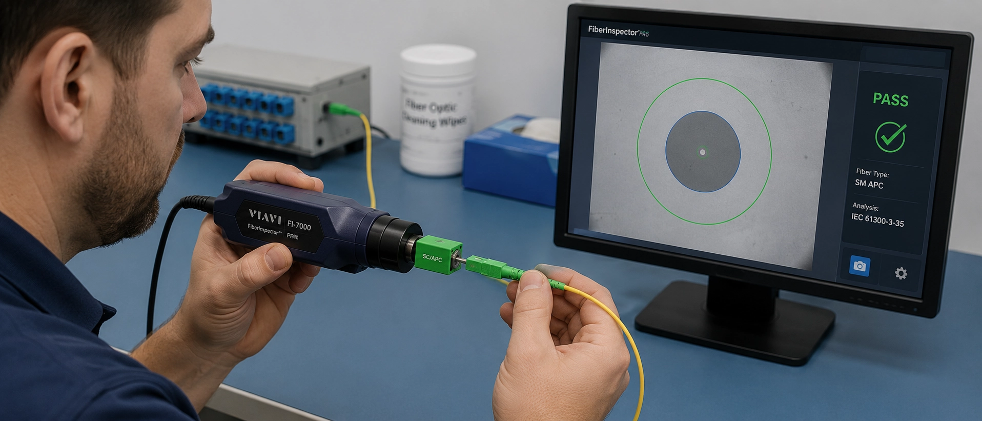
The decision changes when the project specifies what evidence must accompany acceptance. Factory orders may use batch mapping or individual assembly mapping. Field acceptance may rely on a connector inspection result plus the specified optical measurement. Qualification work may require individual mapping, defined wavelengths, and a controlled record format.
That evidence granularity should be decided before production or installation starts, not after a shipment is disputed.
Visual Inspection Does Not Replace IL and RL
Inspection tells you about visible end-face condition; insertion loss and return loss tell you about optical performance.
IEC 61300-3-35:2022 explicitly separates those functions. Visual inspection is additional to optical performance measurements, and a connector cannot be rejected only because visual inspection fails when the specified optical performance determines usability. (IEC)
This creates three engineering decisions. A visibly contaminated connector should have the contamination removed before mating or controlled optical acceptance testing. A visually acceptable connector still requires IL/RL when the specification calls for measured optical qualification. A connector with a persistent, non-removable visual feature should move to the project's stated acceptance method rather than remain in an endless cleaning loop.
If this inspection occurs after fusion splicing, the next step is the optical acceptance workflow rather than another microscopy section. The fiber connector inspection pass/fail criteria should be read together with the project's post-splice IL/RL requirements.
At Higher Optical Power, Contamination Is More Than a Cosmetic Defect
A Journal of Lightwave Technology study at 1550 nm found no damage in clean standard PC/APC connectors during 10-minute exposures at 1 W or 3 W under its experimental conditions, while deliberately carbon-black-contaminated samples showed severe optical failure signatures at approximately 50 mW. Those values are experimental observations, not universal connector power ratings. (Journal of Lightwave Technology)
A later Journal of Lightwave Technology study investigated house-dust contamination and a procedure combining cleaning, end-face observation, insertion-loss measurement, and return-loss measurement. Under that experiment, connectors exhibiting IL < 0.5 dB and RL > 45 dB after the proposed cleaning process tolerated 5 W. Again, the useful conclusion is the relationship among contamination, inspection, optical performance, and power, not "5 W is safe for every connector." (Journal of Lightwave Technology)
For telecom links operating below those experimental power levels, the engineering boundary still holds: contamination, visual condition, and measured optical performance are separate variables. The research demonstrates why power level must remain part of the test context rather than being inferred from a clean microscope image.
What a Traceable Pigtail Inspection Record Should Show
A PASS screenshot without traceability proves much less than buyers usually think.
The report becomes useful when the buyer can connect the inspection result to the assembly that was produced or shipped. If inspection documentation is part of acceptance, the required record structure should be defined before production.
| Record field | Why it matters |
|---|---|
| Connector / polish / fiber configuration | Confirms that the inspection profile and optical criteria belong to the actual product |
| Lot number or individual connector/assembly ID | Connects the result to the delivered material |
| End-face image and Pass/Fail result | Preserves the observed visual condition rather than only a summary statement |
| Inspection system/profile or controlled internal method | Makes the result reproducible and auditable |
| Initial result / after-clean result / final disposition, where recorded | Distinguishes removable contamination from a persistent feature |
| IL/RL criteria and measured result when required | Separates visual cleanliness from optical acceptance |
| Test wavelength and method when required by the specification | Prevents an optical result from being detached from its test condition |
| Record delivery format | Prevents the buyer and supplier from discovering after shipment that different documentation was expected |
If traceability is an acceptance requirement, put record granularity, lot or connector mapping, required IL/RL criteria, wavelength, and deliverable format into the PO or approved specification before production.
A useful requirement can be written in plain engineering language: "Provide connector end-face inspection evidence for the agreed lot or serial granularity and the specified optical-test results, with the delivered record mapped to the shipment identification." The actual numeric acceptance criteria should come from the project specification rather than from a generic blog template.
Documentation scope is order-specific. EVOLUX lists finished connector end-face inspection, insertion-loss testing, return-loss testing, and batch or individual test records as options that can be discussed according to the confirmed order requirements. If these records are acceptance deliverables, define them in the approved specification before production. (fiber connector inspection for manufacturing QA)
Final Inspection Decision
A dependable fiber connector inspection for pigtails workflow is a decision process, not a cleaning count. Inspect both mating interfaces, clean when the observed condition is removable, reinspect the result, stop treating a permanent feature as dirt, and use the specified optical qualification when usability rather than visual appearance is the acceptance question.
Cleanliness should be proven by inspection, while usability should be decided by the complete acceptance requirement.
If inspection and IL/RL documentation are part of incoming QC or project acceptance, request a sample pigtail inspection or optical-test record format first and confirm whether the required lot or individual mapping can be supplied. That lets the QA team review the evidence structure before an order is released.
Once the documentation requirement is clear, send the connector type, polish, fiber specification, quantity, test wavelength, and required acceptance criteria for quotation. That keeps the RFQ tied to an engineering requirement instead of adding "100% tested" after the commercial terms have already been agreed.
FAQ
What is fiber connector inspection before mating?
It is microscopic examination of the connector end face for contamination, scratches, and defects before use or qualification.
Should a new fiber pigtail be inspected before connection?
Yes. A protective cap reduces exposure but does not prove that the connector end face is clean when the cap is removed.
Should I clean a fiber connector before inspecting it?
Inspect first, clean when the observed condition requires it, and reinspect before mating.
Does failing IEC 61300-3-35 visual inspection mean the connector must be replaced?
No. IEC 61300-3-35:2022 states that a connector cannot be rejected solely because it fails visual inspection and that specified optical performance determines use.
When should insertion loss and return loss be checked?
Check IL and RL whenever the project or product specification requires optical qualification, especially when visual inspection alone cannot resolve acceptance.