When a Splice Looks Fine and Still Fails Downstream
It's a pattern we see often enough in acceptance paperwork: a link measuring 71.794 dB/km at 1310nm, well outside the pass threshold, even though the individual splice events along the route looked unremarkable on paper. The worst single splice loss recorded was 0.342dB, nowhere near catastrophic on its own.The link failed anyway, because acceptance isn't decided splice by splice. It's decided by what the end-to-end budget looks like once every event is added up, and that's a number OTDR traces alone don't hand you.
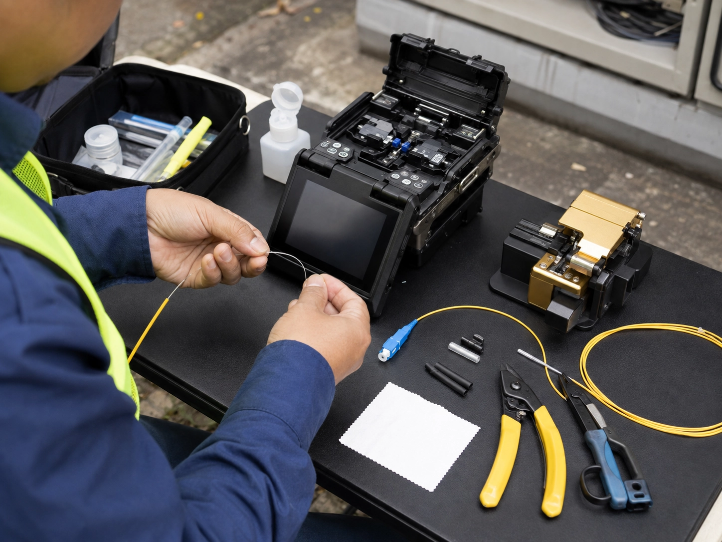
This is exactly where fiber pigtail testing after splicing usually breaks down: teams check that each fusion joint looks clean under the splicer's estimate, skip a formal insertion loss measurement, and assume the link is ready.This exact question comes up often enough in the field that it's worth stating plainly: it usually isn't the splice quality that fails, it's the absence of a measurement that would have caught the cumulative loss before the customer did
What OLTS and OTDR Each Actually Measure
The two instruments get lumped together constantly, and that's the root of most confusion in the field. An Optical Loss Test Set (OLTS) injects light from a reference source at one end and reads it with a power meter at the other, giving you a single end-to-end insertion loss number for the whole link. An OTDR does something different: it sends a pulse down the fiber and reads the backscattered light, building a trace that shows you where each event (splice, connector, bend, break) sits along the length, and roughly how much loss each one contributes.
That distinction determines what each tool is actually good for. OLTS tells you whether the finished link, as a whole, meets the loss budget. It's a pass/fail measurement. OTDR tells you where a problem is and what kind of event caused it. It's a diagnostic map, not a certification result. Confusing the two is why some technicians treat a clean-looking OTDR trace as proof the pigtail splice testing is complete, when the standard bodies drew a much sharper line (Fiber Optic Association).
For readers coming from broader pigtail testing basics rather than the splicing-specific workflow, our general guide to testing a fiber optic pigtail covers visual inspection and return loss testing in more depth than this article does.
TIA-568.3-D and Why Tier 1 Is Non-Negotiable
TIA-568.3-D splits fiber testing into two tiers, and the split isn't cosmetic. Tier 1 is OLTS insertion loss testing, and it's the mandatory certification requirement for every link. Tier 2 is OTDR testing, and it's classified as optional: recommended for documentation and troubleshooting, but not accepted on its own as proof a link is certified.
That's the point worth remembering: an OTDR trace, however clean, does not satisfy acceptance testing under the standard. Some project specs still get written as if it does, particularly on PON deployments where a handful of suppliers accept bidirectional OTDR results as sufficient evidence, but that's a scoped exception, not the general rule. Outside PON, don't count on it: most supervising engineers and clients won't sign off on OTDR-only certification, no matter what a vendor's marketing page implies. Some test-equipment vendors serving TIA-568.3-D certification work have said this possibility, elevating OTDR to something closer to Tier 1 status, is under discussion at the standards-committee level, though nothing has moved past discussion. Tier 1 OLTS testing remains the only test format written into the standard as mandatory today.
Running a Fiber Pigtail Insertion Loss Test After Fusion Splicing
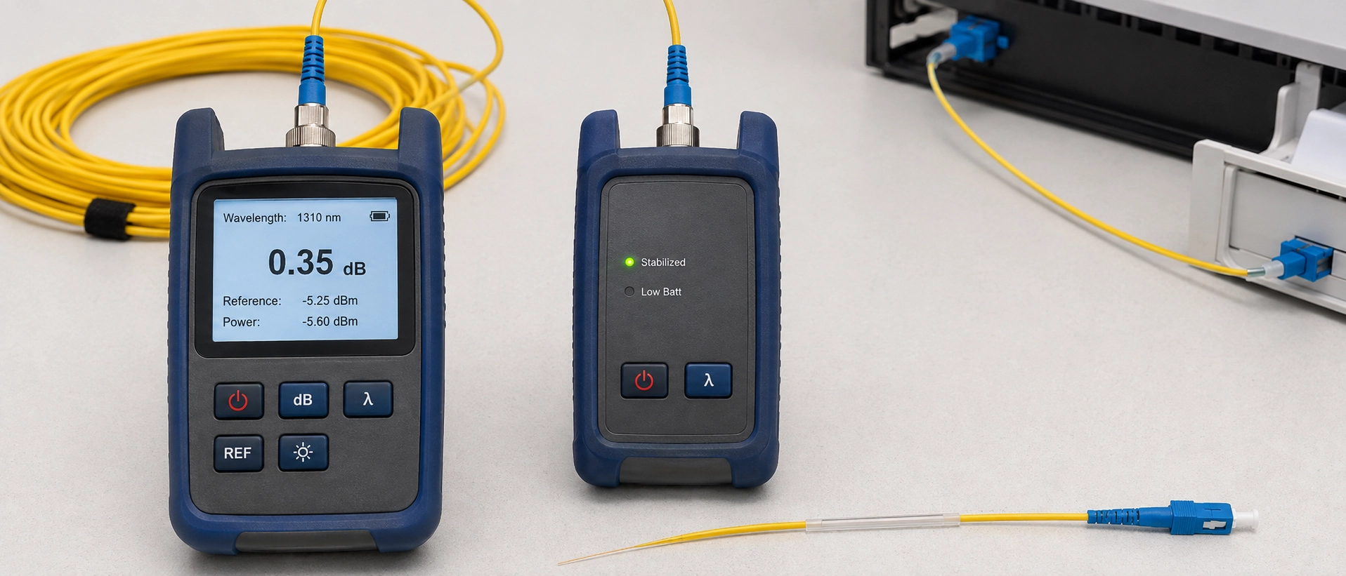
Get the order wrong on a fiber pigtail insertion loss test after fusion splicing, and the reading you take won't mean what you think it means. Reference the light source and power meter together first, using a known-good reference cord, so the "0 dB" baseline reflects the test set and not an uncalibrated jumper. Most single-mode acceptance testing uses the 1-jumper reference method; the 3-jumper method reads a slightly different loss number for the same physical link, so pick one and stay consistent through the project. Mixing the two mid-project is a common reason before-and-after loss comparisons stop lining up.
Then connect through the spliced link and take a reading at each operating wavelength: 1310nm and 1550nm for single-mode, 850nm and 1300nm for multimode, because loss at a splice or bend is wavelength-dependent, and a single-wavelength reading can miss a marginal joint entirely.
Test in both directions where the project allows it. A splice with a slight core mismatch can read negative loss from one direction and out-of-spec loss from the other, so a one-direction test only ever catches half of that picture. Record both readings, not just the better one. Some project specs, particularly dark fiber lease agreements, explicitly require bidirectional documentation with the technician's signature and test-set model number attached, and retrofitting that after the fact is far more work than capturing it during the original acceptance test.
Verifying the Splice Event on OTDR
After the OLTS gives you a pass or fail number for the spliced pigtail, the next job is confirming that the loss it measured actually sits at the splice point, and not somewhere else on the link.Launch cable selection is the first thing that trips people up here: use 500m to 1km of launch fiber ahead of the splice under test, because the OTDR needs that distance to recover from its initial pulse and settle into an accurate reading before it reaches the event you actually care about. Skip the launch cable and the splice loss reading near the front of the link becomes unreliable or invisible.
Dual-wavelength testing is the other habit worth building in. Testing at both 1310nm and 1550nm isn't just for loss confirmation, it's a diagnostic tool in its own right. A splice with unusually large loss differences between the two wavelengths is more often a sign of macrobend stress, commonly from a splice tray coiled too tightly, than a poor fusion joint. Catching that distinction on-site saves a re-splice that wouldn't have fixed the actual problem.

The Splice That the OTDR Never Saw
Here's a detail that catches even experienced technicians off guard: a genuinely good fusion splice in a pigtail assembly can be effectively invisible on an OTDR trace.When splice loss drops below roughly 0.05dB, which a properly fused, mode-field-matched joint routinely achieves, it can fall under the OTDR's default event detection threshold. Most OTDRs ship with a default event threshold somewhere around 0.1 to 0.15dB, so a suspected low-loss splice is worth chasing by lowering that setting toward 0.02 to 0.05dB and re-running the trace; the exact figure still depends on your OTDR model and its dead-zone settings, so confirm against your own equipment rather than treating any number here as universal.
The other pitfall worth flagging sits in the acceptance threshold itself, not the instrument. Published contract language for dark fiber projects shows more tolerance than most engineers assume: one lease agreement we reviewed allowed up to 0.5dB splice loss when mode field diameters were matched, rising to 0.8dB when they weren't (lawinsider.com), figures well above the sub-0.1dB "textbook" fusion splice loss most training material quotes. Knowing which number your specific contract actually requires, rather than assuming the tightest published figure applies, is the difference between a splice you re-work unnecessarily and one you correctly sign off.
A related trap is loss that's real but misattributed. One recurring troubleshooting pattern involves several mechanical splices placed close together along a run, each one individually within spec, but stacked tightly enough that the cumulative loss pushes the link over budget. An OTDR trace read casually can make that look like a single bad event; read carefully, it's several small, technically-passing events adding up to a failing link.
Acceptance Thresholds: The Fiber Splice Acceptance Testing Checklist
Pulling the numbers together into a single fiber splice acceptance testing checklist makes field decisions faster than flipping between a standard document and a contract PDF mid-test.
| Measurement | Typical value | Notes |
|---|---|---|
| Fusion splice loss | Under 0.1dB | Below ~0.05dB, raises OTDR detection risk, lower the threshold setting |
| Mechanical splice loss | 0.2–0.5dB | Stacking multiple close together can push cumulative loss over budget |
| Connector loss | 0.2dB or higher | Higher baseline than a good fusion splice by design |
| Contract tolerance, matched MFD | Up to 0.5dB | Seen in dark fiber lease specifications, not universal |
| Contract tolerance, mismatched MFD | Up to 0.8dB | Applies specifically to mode-field mismatch scenarios |
| OLTS testing (Tier 1) | Pass/fail vs. link budget | Mandatory under TIA-568.3-D |
| OTDR testing (Tier 2) | Diagnostic, not certifying | Optional under TIA-568.3-D, except in some PON-specific specs |
Treat the contract-tolerance rows as a reminder to check the actual project spec rather than a substitute for it. Acceptance numbers vary by client, and the standard sets a floor, not a universal ceiling.
A Field Case: From Alarm to Root Cause
A link that kept tripping loss alarms after commissioning turned out to be a useful illustration of why OTDR and OLTS need to be read together. This is the kind of pigtail acceptance test outcome that's easy to misdiagnose without both instruments.The OLTS end-to-end reading confirmed the link was out of budget; that part was unambiguous. The OTDR trace was where the real diagnostic work happened: instead of one obvious failure point, it showed a cluster of four mechanical splices spaced within about two meters of each other, each individually inside its own 0.3–0.4dB loss spec, collectively pushing the link roughly 1.2dB over budget. It took two passes, 1310nm first, then a 1550nm retest to rule out a bend-stress false read, before the pattern of stacked small losses was clear rather than a single bad joint. Replacing the cluster with a single fusion splice brought the link back within budget immediately. Neither instrument alone would have told the full story: the OLTS confirmed there was a problem, and the OTDR located what was actually causing it.
That kind of event tracing applies well beyond splice-specific scenarios, and it's the same discipline worth applying any time a link fails intermittently after commissioning.
Building Testing Into the Supply Chain, Not Just the Field
Most of what goes wrong in post-splice acceptance testing traces back to a gap upstream of the field crew: pigtails that leave the factory without a documented insertion loss record are harder to trust once they're spliced into a live link, because there's no baseline to compare the field reading against.
We've been on the wrong side of that gap ourselves. During one outgoing QC run, a batch of low-loss splices in a custom pigtail assembly read clean on the OTDR trace, no events flagged, simply because the loss was too low to clear the default threshold, the same blind spot covered above. It only surfaced when a technician cross-checked the OTDR result against the OLTS insertion loss figure and the two didn't agree. That mismatch is part of why every finished pigtail we ship now carries both an OLTS and an OTDR result, not just one or the other.
Our production process runs that dual test on every finished pigtail before it ships, a practice we've held to for more than a decade of shipping spliced pigtail assemblies.It tracks with the attenuation test procedures in IEC 61300-3-34 and with the splice-loss guidance connector manufacturers publish for field crews.This is our own factory-floor data, not an industry-wide figure: connector insertion loss on our line typically lands in the 0.15–0.25dB range, with a 0.3dB ceiling we don't ship above. We can hand that over as a traceable test report alongside the product, worth checking before you assume a supplier's datasheet matches what actually left their factory.
If your current acceptance testing keeps surfacing splice-side loss that doesn't match what a supplier's datasheet promised, it's often worth checking whether the pigtails themselves shipped with individual test records at all. You can review our fiber optic pigtail product range and request the accompanying OTDR trace samples directly.
FAQ
What's the difference between OLTS and OTDR for testing fiber pigtails after splicing?
OLTS measures total end-to-end insertion loss and is the TIA-568.3-D required Tier 1 test for acceptance. OTDR locates and characterizes individual splice events but is not accepted alone for certification.
Why can't my OTDR see a low-loss fusion splice?
When splice loss is very low, often under 0.05dB, it can fall below the OTDR's default event detection threshold. Lowering the loss threshold setting typically reveals the event.
What insertion loss is acceptable for a spliced fiber pigtail?
Fusion splices typically show under 0.1dB loss, while connector loss is usually 0.2dB or higher. Some project contracts allow up to 0.5dB for matched fiber and 0.8dB for mismatched mode field diameters.
Is OTDR testing alone acceptable for fiber acceptance certification?
No. TIA-568.3-D requires OLTS (Tier 1) testing for certification. OTDR (Tier 2) is optional and used mainly for troubleshooting, except in some PON deployment scenarios where certain suppliers accept it.