Answer first. To splice fiber pigtails in a patch panel: confirm the enclosure is splice-ready, confirm trunk and pigtail glass match, calibrate the splicer at the work position, then work the ten numbered steps below from cable entry to labelled port. Hold each fusion joint under 0.1 dB as a working target, knowing ANSI/TIA-568.3-E permits up to 0.3 dB per splice for premises cabling and that the project specification outranks both figures. Measure every OTDR splice event from two directions and average, because single-direction readings on dissimilar fiber are wrong in a predictable direction rather than merely imprecise.
Pre-Work Checks Before You Splice Fiber Pigtails in a Patch Panel
Most of what reaches our applications desk is not a splicing problem. It is a purchasing or planning problem that only became visible once the crew was standing at the splicer with a cable already opened. Three checks take ten minutes and remove almost all of them.
| Condition | What to verify | Stop work if |
|---|---|---|
| Enclosure is splice-ready | Tray mounting points, splice holder capacity, slack storage channel, bend-radius guides all present | Any one of the four is missing. A direct-termination chassis without tray mounting or slack channel cannot practically be converted on site, though some modular enclosures accept an add-on tray kit. Confirm against the enclosure datasheet before assuming either way |
| Fiber types match end to end | Trunk and pigtail are both single-mode, or both the same multimode category. Check the cable print and the pigtail label, not the jacket color | Core geometries differ. A single-mode to multimode joint does not simply run lossy. Depending on direction, launch conditions and receiver margin it produces anything from severe unacceptable loss to a link that will not come up at all |
| Splicer is calibrated for this room | Arc calibration run at the actual work position, electrode condition and arc count checked | Calibration was last run in different temperature or altitude conditions |

Three failure modes account for most of the pigtail complaints and returns we handle, and all three are decided before anyone opens a cable: a panel ordered as a direct-termination chassis when the design assumed splice trays, a multimode pigtail set ordered against a single-mode trunk because the order referenced jacket color rather than the cable print, and 0.9 mm legs replaced by 2.0 mm legs on price grounds until the tray no longer closes without pinching. None of the three is fixable with a better splicer.
Panel selection in particular is a purchasing decision made weeks before anyone opens a cable, which is why choosing a splice-ready patch panel or ODF belongs inside the splice plan. Mode compatibility is the same kind of decision: the difference between single-mode and multimode pigtail construction is set at the order stage, not at the tray.
What a Factory-Polished Fiber Pigtail Buys You That Field Termination Doesn't
The case for pigtail termination is a manufacturing argument, not a convenience argument. Ferrule end-face geometry, meaning radius of curvature, apex offset and fiber height, is set on polishing equipment running dozens of connectors at a time under controlled pressure and film sequence.
What we can state precisely is the specification and the process behind it. Every terminated assembly on our line passes end-face inspection, insertion loss measurement, return loss measurement, continuity, polarity verification and color-sequence confirmation before packing. The single-mode specification limits are ≤0.2 dB insertion loss and ≥50 dB return loss for UPC, ≤0.3 dB and ≥60 dB for APC. Those are ceilings written into the product specification rather than a claimed field average. The measured distribution belongs in the batch record that ships with the order, and we will send an anonymised batch report with test wavelength and instrument type on request, because a distribution you can inspect is worth more than a number quoted in a blog paragraph.
A field-polished connector can reach those numbers. What it cannot do is reach them consistently, connector after connector, on a rooftop in July with a hand polishing puck and no interferometer. That consistency is the whole reason a factory-terminated fiber pigtail spliced to the trunk beats terminating the trunk directly. The background on what a fiber pigtail is used for across FTTH, ODF and data center builds covers the component side. This article stays on the procedure.
Bench Setup and Consumable Life Before You Splice Fiber Pigtails
Once basic competency is established, consumable condition becomes the repeatable source of drift in splice results. The observable signal is not a single bad joint. It is a trend: estimated loss climbing steadily through the second half of a tray, or reported cleave angle degrading across three consecutive joints. When you see either, stop and check blade position and arc count before you change anything about your technique.
The table below lists what the bench needs and, more usefully, when each item stops being trustworthy, with the authority each figure actually rests on.
| Item | Specification that matters | Service point | Basis |
|---|---|---|---|
| Fusion splicer | Core alignment for single-mode work | Arc calibration on arrival and after temperature or altitude change | Splicer manufacturer's operating manual |
| Electrodes | Matched to splicer model | Replace at the arc count your splicer's own counter and manual specify. Do not work to a generic industry number, because the figure differs by model and by electrode type | Splicer manufacturer's maintenance schedule |
| Precision cleaver | Capability below 0.5° | Rotate blade position on schedule, replace when reported cleave angle drifts upward | Cleaver manufacturer's blade-life table |
| Strippers | Separate tools for 0.9 mm tight buffer and 250 μm coating | Inspect jaws for coating build-up each shift | Field practice |
| Cleaning consumables | 99% isopropyl alcohol, lint-free wipes | Fresh wipe face per splice. Contamination left on the glass is vaporised by the arc and can redeposit inside the joint as an inclusion | Splicer and fiber manufacturer cleaning guidance |
| Protection sleeves | Inner diameter matched to fiber, length matched to the tray holder | Confirm sleeve seats in the holder before the first joint | Sleeve and tray manufacturer specifications |
| VFL, OLTS, OTDR | VFL for continuity and macrobend hunting, OLTS for certification, OTDR for characterization | Meter calibration current | ANSI/TIA-568.3-E test tiers |
| Labeling | Port and strand identification at both panel faces | Applied before the tray closes | Project labeling specification |
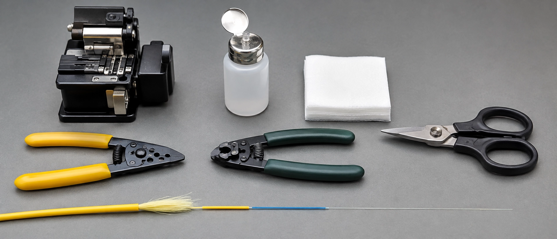
One detail is worth stating plainly because it costs crews an hour when they get it wrong: the heat-shrink sleeve goes onto the fiber before the fiber goes into the splicer. There is no recovery from remembering afterwards.
Fiber Pigtail Fusion Splicing Step by Step: Ten Numbered Steps With Pass Criteria
This is the working order used when we fusion-splice fiber pigtails during customer trials and sample qualification in our own applications lab, on 12-fiber and 24-fiber loose-tube trunk into 1U and 2U tray enclosures with 40 mm and 60 mm protection sleeves. Each step carries a pass criterion and a redo trigger, because a sequence without judgement points is just a description. The same order applies to a single-mode pigtail splicing procedure for FTTH terminal boxes, where only the tray count and fiber count change.
| # | Action | Pass criterion | Redo trigger |
|---|---|---|---|
| 1 | Bring the trunk into the panel, strip the outer jacket to the planned window, secure the sheath at the entry gland, and bond metallic strength and central members to the enclosure ground point per the cable and enclosure manufacturers' instructions and the bonding rules in force at the site. Dielectric strength members are not bonded, so identify which type you have before touching a lug | Cable cannot move under hand pressure, bonding method matches the member type actually present and the manufacturer's instruction | Any movement at the gland, or a dielectric member treated as metallic |
| 2 | Ring-cut and remove buffer tubes, remove all gel residue with 99% IPA, route each tube to its assigned tray | No visible residue on any fiber, tubes seated in their tray entries | Gel felt or seen on the fiber |
| 3 | Lay trunk strands and pigtail legs out in matching color order on the bench before any tool touches glass | Both sets read in the same sequence, position by position | Any ambiguity in strand identity |
| 4 | Slide the protection sleeve onto the pigtail leg | Sleeve on, boot side clear of the splice zone | Sleeve missing at step 8 |
| 5 | Strip coating from both fibers to the length your splicer holder and sleeve require, typically in the 30–40 mm region. Splicer holder geometry, cleave length and sleeve length together set the correct figure for your equipment | Bare fiber length seats correctly in the holder with the cleave point at the intended position | Fiber too short to reach the holder datum, or so long it fouls the sleeve |
| 6 | Clean with a single unidirectional wipe, fresh wipe face each time | No audible or visual drag, no residue | Any second pass over the same wipe face |
| 7 | Cleave both ends | Splicer reports a flat, perpendicular face. Below 0.5° is where results become consistently repeatable, and the cleaver manufacturer's stated angle capability is the reference for your tool | Angle report drifts upward, or the face shows a chip, lip or hackle |
| 8 | Run the arc with the correct fiber profile selected | Splicer estimate consistent with the other joints on the same tray | A visible line, bulge or bubble in the joint image |
| 9 | Center the sleeve over the joint with the strength rod aligned, run the oven cycle specified for that sleeve diameter | Sleeve fully shrunk, no trapped air, joint centered on the rod | Off-center joint or incomplete shrink |
| 10 | Seat the sleeve in its holder, coil slack from the middle outward to both sides, close the tray, dress pigtail legs into the adapter plate, cap unused adapters, label both faces, then test | Loops lie flat, no tension at the joint, bend radius at or above the cable manufacturer's minimum | Any loop tighter than the cable's specified minimum bend radius |

A visible line, bulge or bubble means re-cleave, not re-heat.
Two judgement points inside that sequence deserve emphasis. The splicer's estimate at step 8 is an estimate produced by image analysis, not a measurement. It is excellent for deciding whether to redo a joint on the spot, and it is not acceptance evidence. And step 10 is deliberately ordered so that labeling precedes testing, because test reports that cannot be traced to a port are re-work in disguise.
Fiber Pigtail Color Sequence and Getting Polarity Right the First Time
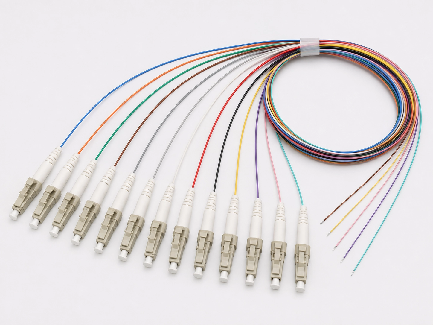
Color identification is the cheapest error-prevention mechanism in the procedure, and it only works when the pigtail set follows the same convention as the trunk. The twelve-position sequence specified in ANSI/TIA-598-D runs blue, orange, green, brown, slate, white, red, black, yellow, violet, rose, aqua, with cables above twelve fibers repeating the sequence per buffer tube and adding tracer marking.
Anyone working out how to install a 12-fiber pigtail in a patch panel should treat the color set as a specification item rather than a field convenience. Two cautions apply. IEC and TIA conventions do not agree at every position, so a build that mixes cable from one convention with tails from another needs the mapping written down before splicing rather than discovered during testing. And the convention that arrives is the one the purchase order named. We supply 12-color pigtail sets to either sequence, which means the decision is made at RFQ, not at the tray.
Acceptable Splice Loss for a Fiber Pigtail: Which Document Are You Actually Held To
Use 0.1 dB per joint as the working target when you splice fiber pigtails, and expect a modern core-alignment splicer on clean single-mode glass to land well below it. Contract acceptance, however, follows the project specification and the edition it names, not this paragraph. Three thresholds circulate, they come from documents of very different authority, and the project file decides which one applies.
| Threshold in use | Value | Governing document | Status |
|---|---|---|---|
| Premises and data center cabling | 0.3 dB per fusion splice, 0.75 dB per mated connector pair at standard grade | ANSI/TIA-568.3-E | Published standard limit. The same standard sets a tighter allowance where a reference-grade cord mates to a standard-grade connector, so read the clause that matches your test method (Fluke Networks) |
| Outside plant and operator practice | 0.1 dB per splice, frequently with a 0.05 dB link average, sometimes tighter on feeder routes | The operator or funded-program specification itself | Contract target, not a generic standard limit. Telcordia GR documents are often named in these contracts, but there is no Telcordia acceptance value that applies outside the contract that cites it. If your contract names a GR document, take both the figure and the edition from that clause |
| Design planning value | 0.15 dB per single-mode fusion splice, with experienced technicians well below 0.1 dB | Fiber Optic Association guidance (FOA) | Planning figure for budget calculation |
The practical rule that follows: the project specification outranks every generic figure in this table, including ours. Where the two conflict, the specification wins and the argument is over.
The spread between 0.3 dB and 0.05 dB is where acceptance disputes live, and the reason is arithmetic. A PON link carrying a high split ratio has little margin left after splitter loss, connector pairs and route attenuation, so every joint landing at 0.15 dB instead of 0.05 dB is spending budget a future node was going to need. On a 90-meter commercial LAN run, the same joint is irrelevant.
One more piece of arithmetic, stated carefully. In a worst-case budget calculated at the standard's maximum permitted values, the mated connector pair at 0.75 dB consumes more than twice what a splice does at 0.3 dB, so the connector interface, not the fusion joint, is the larger line item. Real components usually perform far better than either ceiling, which is exactly why the connector end of every fiber pigtail we ship is measured rather than assumed.
Fiber Pigtail Splice Testing: Tier 1, Tier 2, and Why One-Direction OTDR Reports Get Rejected
Two testing tiers exist when you certify fiber pigtail splices, and they are not interchangeable. Tier 1 is insertion loss certification with an optical loss test set, and it is what certifies the link. Tier 2 is OTDR characterization, and it is diagnostic. A trace showing every splice below 0.05 dB is useful evidence and it does not substitute for Tier 1 results.
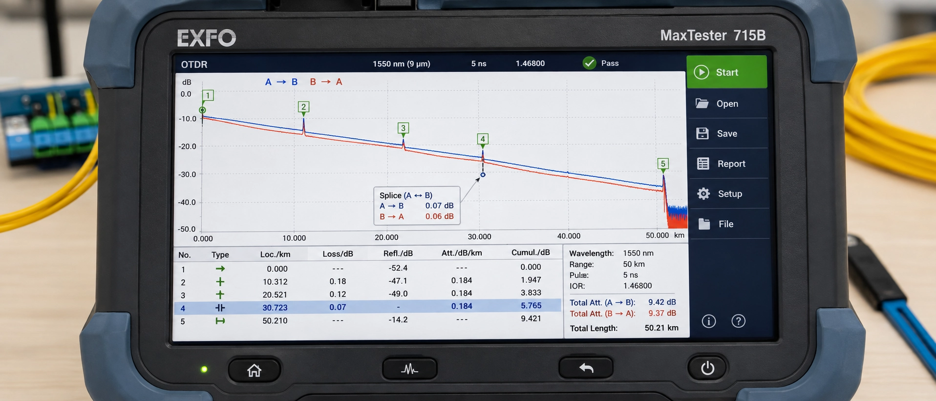
The second rule catches more crews than the first. OTDR splice loss must be measured from both directions and averaged. This is the measurement method the procedure is built on, and single-direction results on a link containing dissimilar fiber are not merely imprecise, they are wrong in a predictable direction (Corning). Which brings us to the reading that makes good technicians redo good joints.
The Gainer: When Fiber Pigtail Splice Readings Lie
An OTDR does not measure splice loss on a fiber pigtail joint. It measures backscatter on either side of an event and infers loss from the step. When the two fibers have different mode field diameters, their backscatter coefficients differ, and the inferred step is contaminated by that difference.
Measured from the larger-MFD side toward the smaller, the instrument reports an apparent gain, meaning power that cannot exist. Measured the other way, it reports an inflated loss. Averaging the two directions removes the artifact and leaves the real figure.
A category-level comparison is not sufficient evidence of a mode field difference, and this is where most field explanations go wrong. ITU-T requires a nominal MFD and a tolerance to be declared at 1310 nm within a permitted range, and the permitted ranges for standard single-mode and bend-insensitive categories overlap (ITU-T G.652). The overlap is not theoretical: Corning's SMF-28 Ultra declares 9.2 ± 0.4 μm at 1310 nm while being fully compliant with G.652.D and exceeding the G.657.A1 bend requirement, so "G.657 fiber" tells you nothing on its own about the mode field you are splicing into. Other bend-insensitive designs, particularly in the B categories, do sit lower.
So the working rule is not "expect a gainer whenever G.657 meets G.652". It is: read the declared nominal MFD on both datasheets, the trunk cable's and the pigtail's, and expect directional asymmetry when those two declared values differ meaningfully. Category names will mislead you, datasheets will not. This is why we print fiber grade, G.652D, G.657A1 or G.657A2, on the pigtail specification, and why asking a supplier for the declared MFD is a reasonable question rather than a pedantic one.
Troubleshooting Fiber Pigtail Splicing Faults: Verify, Then Act
| Symptom | Verify first | Most likely cause | Action | Re-splice required? |
|---|---|---|---|---|
| Splicer estimate above 0.1 dB, visible inclusion | Inspect the joint image before cutting anything | Contamination vaporised into the joint | Re-strip, clean with fresh IPA, re-cleave, re-splice | Yes |
| Repeated bad-cleave messages | Check the reported cleave angle trend across the last several joints | Blade wear or inconsistent strip length | Rotate blade position, verify strip length, inspect the face | Yes, after tool correction |
| Arc instability, loss creeping upward across a shift | Read the arc counter and run arc calibration | Electrode wear or contamination | Clean electrodes, replace at the manufacturer's specified count | Only the affected joints |
| Alignment errors on visibly clean fiber | Inspect V-grooves and holders | Debris in the grooves | Clean with alcohol and swab, re-seat | No, re-run the same fibers |
| Sleeve loose or joint off-center after the oven | Confirm sleeve diameter against fiber and holder | Wrong sleeve size or oven profile | Cut back, correct sleeve, rerun the specified cycle | Yes |
| Loss appears only after the tray is closed | Trace with a VFL before reopening the joint | Macrobend from over-tight coiling or a pinched leg | Re-coil to the cable's minimum bend radius and re-dress | No |
| High loss one direction, gain the other | Compare declared MFD on both datasheets | Mode field difference between trunk and pigtail glass | Test bidirectionally and average before touching the joint | No |
| No light on one strand | Re-check the color mapping and the fiber type on both sides | Crossed strand or mode mismatch | Correct the mapping. If the fiber types differ, the strand must be re-planned rather than re-spliced | Re-plan, not re-splice |
Fiber Pigtail Splice Tray Routing, Slack and Rack Reality
Use splice-on connectors instead of fiber pigtails when tray positions, rather than optical loss or unit cost, are the binding constraint. Splice-on connectors do not need an external protection sleeve or a holder position to store it (Fluke Networks), and in a 1U enclosure with a tray already carrying a full complement of joints, that is decisive.
The boundary runs the other way under four conditions: panel space is adequate, cost per termination matters at volume, the connector interface may need to change later in the life of the plant, or you want the connector end to be a factory-tested article with documented loss figures rather than a field-produced one.
Three deployment situations make the fiber pigtail vs splice-on connector decision in a patch panel concrete. In an FTTH cabinet or terminal box, pigtails are the preferred route when the box ships with an integral tray, the holder count covers the fiber count with at least one spare position, the sleeve length you buy actually seats in that holder, and the design calls for a factory-terminated connector at the port. Change any one of those and re-run the comparison. In a carrier ODF at a data center entrance, incoming plant is conventionally spliced to panels loaded with factory-terminated tails and the architecture assumes trays exist, so anyone asking how to splice fiber pigtails in an ODF is working inside a design that already answered this question. In a compressed enterprise IDF where a 1U panel has been specified for 48 fibers, the arithmetic frequently does not close, and the real choice is between a deeper enclosure and splice-on connectors. That trade-off is the same one behind comparing a patch panel against an ODF at design stage.
Whether the arithmetic closes in your specific case depends on three variables no general article can supply: the holder capacity of your tray, the length of the protection sleeve you are using, and the routing path from holder to adapter. Send us the panel model, tray count and fiber count, and we will work the slack and length figures against those three and send back a recommended pigtail length and fiber sequence for that enclosure, together with the measurement worksheet we used to get there.
Specifying Fiber Pigtails That Splice Cleanly
Eight specification lines determine how a fiber pigtail behaves on the bench, and every one of them shows up later as either speed or rework at the tray.
| Specification | Why it changes the splice job |
|---|---|
| Connector type | LC, SC, FC, ST, E2000 and others, matched to the adapter plate already specified rather than to the transceiver |
| Polish | UPC for standard digital links, APC where back reflection matters, as in PON and RF video overlay. The difference between APC and UPC end-face geometry primarily changes return loss. Insertion loss still depends on end-face geometry, ferrule concentricity, cleanliness and the quality of the mating connector |
| Fiber grade and declared MFD | G.652D, G.657A1 or G.657A2, with the nominal MFD stated, so OTDR results are interpretable against the trunk |
| Mode and category | OS1/OS2, or OM1 through OM5. A mismatch here is a re-planning problem, not a splicing problem |
| Cable diameter | 0.9 mm for tray-dense work, 2.0 mm or 3.0 mm where the leg is handled or routed outside the enclosure |
| Jacket material | PVC, LSZH or PE, determined by the project specification, the local fire rating and the installation space. A supplier should not substitute one for another on price grounds without written approval |
| Length and fiber count | Derived by measuring the actual path: holder position, bend-radius route, adapter position, then a service loop long enough for one re-splice at your strip length. Standard offerings run 0.5 m to 3 m in counts from 1 to 48, and the correct figure inside that range comes from the panel rather than from a rule of thumb |
| Color sequence and labeling | TIA-598-D or IEC order, plus project labels, barcodes or QR codes applied in the factory rather than by a technician on a ladder |
Two documentation lines belong on the same purchase order: per-batch or per-unit test records covering insertion loss and return loss, and a certificate of conformity. Both are standard deliverables on our side rather than exceptions, which is what makes the acceptance conversation short when a customer's own OTDR results are under review.
If you want to see what that documentation actually looks like before committing to a supplier, ask us for a custom fiber optic pigtail specification sheet together with a sample IL and RL test report from a comparable batch. It is a faster way to judge a manufacturer than any datasheet claim, including the ones in this article.
FAQ
What is an acceptable splice loss when splicing fiber pigtails?
Under 0.1 dB per splice is the working target for telecom work and 0.3 dB is the ANSI/TIA-568.3-E limit for premises cabling, but the project specification governs where they conflict.
Why does my OTDR show a negative loss on a fiber pigtail splice?
It is a backscatter artifact caused by a mode field diameter difference between the two fibers, and bidirectional averaging removes it.
What cleave angle does a low-loss fiber pigtail splice need?
Below 0.5 degrees is where results become consistently repeatable, provided strip length, holder position and sleeve size are matched to your equipment.
Do I need a special patch panel to splice fiber pigtails?
Yes. The enclosure needs tray mounting, splice holders, slack storage and bend-radius guides, and a direct-termination chassis lacking those cannot practically be converted on site.
Should I use fiber pigtails or splice-on connectors?
Use pigtails when tray space is adequate and cost per port or connector flexibility matters, and use splice-on connectors when tray positions are the binding constraint.
How do I choose the right fiber pigtail length for a rack-mount panel?
Measure the real path from splice holder to adapter position along the bend-radius route, then add a service loop long enough for one re-splice at your strip length.