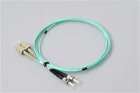
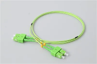
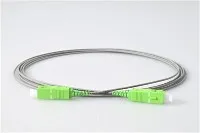
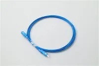
An APC fiber connector is a single-mode connector whose ferrule end-face is polished at an 8-degree angle, so reflected light is steered away from the fiber core instead of straight back at the source. APC stands for Angled Physical Contact. That single piece of geometry - the tilt on the ferrule tip - is the whole reason the connector exists, and it is why APC is the default in FTTH, PON, CATV, and many WDM links where back reflection degrades signal quality or measurement accuracy.
This guide explains what an APC connector is, how the angle controls back reflection, how it compares with UPC, where it actually sits in an FTTH/PON network, and how to specify the right fiber optic connector, patch cord, pigtail, splitter, or adapter so the parts that arrive match the link you are building.
What Is an APC Fiber Connector?

An APC connector is a fiber optic connector with an angled-polished ferrule end-face - almost always 8° for single-mode fiber - rather than a flat one. The ferrule still aligns the two fiber cores with the same precision as any other connector; only the end-face geometry changes. That change is enough to push reflected light out of the core and lift return loss by roughly 10 dB compared with a flat single-mode polish.
In the field, APC connectors are easy to identify by color. A single-mode APC connector body or boot is green, while a single-mode UPC connector is blue. This follows the long-standing industry color convention (TIA-598) that lets installers avoid mixing polish types at a glance. The 8° angle itself is the standard single-mode APC geometry described in most optical fiber connector references.
What Does APC Stand For?
APC stands for Angled Physical Contact, and each word describes the design:
- Angled - the end-face is polished at an angle (8° for single-mode), not flat.
- Physical Contact - under spring load the two ferrules touch with no air gap between the cores.
- Connector - a re-mateable interface between fibers, adapters, panels, or equipment ports.
The angled polish rides on several connector bodies. The common single-mode APC families are SC/APC, LC/APC, FC/APC, and E2000/APC.
How the 8° Angle Controls Back Reflection?
Whenever light crosses a connector interface, a small Fresnel reflection occurs at the glass boundary. With a flat (PC or UPC) end-face, that reflection travels straight back down the fiber axis. Single-mode core diameter is only about 9 µm, so the reflected power couples efficiently back into the guided mode and returns to the transmitter, receiver, or test instrument - exactly where it causes trouble.

Tilt the end-face by 8° and the reflected ray leaves at roughly twice that angle to the fiber axis. That direction lies outside the fiber's acceptance angle, so most of the reflected light radiates into the cladding and is lost instead of being guided back to the source. The practical result is that return loss rises from the ~50 dB range of a good UPC to ~60 dB or better. If you want the full breakdown of how end-face shape changes the reflection path, see this explainer on the difference between PC, UPC, and APC polishing.
Return Loss vs Insertion Loss
Two numbers describe a mated connector pair, and they are not the same thing:
- Insertion loss (IL) - how much optical power is lost passing through the pair. Lower is better.
- Return loss (RL) - how much light is reflected back toward the source. Higher is better (more dB means less reflection).
APC is chosen specifically for return loss. Insertion loss is broadly similar across polish types, so the angle is not about lower through-loss - it is about reflection control. The values below are the figures you will typically see on single-mode datasheets:
| Polish type | Typical return loss | Typical insertion loss |
|---|---|---|
| PC | ≥ 40 dB | ≤ 0.3 dB |
| UPC | ≥ 50 dB | ≤ 0.3 dB |
| APC | ≥ 60 dB | ≤ 0.3 dB |
These are typical commercial grades. Standardized IL and RL grades for connector optical interfaces are defined by the International Electrotechnical Commission (IEC), so for a project order it is worth confirming the exact grade against the supplier's datasheet and test report rather than trusting a category label.
vs UPC Fiber Connectors: Key Differences
APC and UPC can look almost identical apart from color, but the end-face geometry is different, and that difference drives everything else.
| Feature | APC connector | UPC connector |
|---|---|---|
| Full name | Angled Physical Contact | Ultra Physical Contact |
| End-face | 8° angled polish | Flat (domed) polish |
| Typical color (single-mode) | Green | Blue |
| Typical return loss | ≥ 60 dB | ≥ 50 dB |
| Best for | FTTH, PON, CATV/RFoG, WDM, optical test | Ethernet, transceivers, switches, data-center cabling |
| Mating rule | Mate only with APC | Mate only with UPC |
The one rule that matters most: never mate APC to UPC. An 8° face cannot seat flat against a 0° face, so you get an air gap, high insertion loss, unstable return loss, and a real risk of chipping the ferrule edge - even though both connectors are the same form factor.
Which Polish Should You Choose?
Rather than asking which is "better," match the polish to the situation:
| Situation | Recommended polish |
|---|---|
| PON splitter output through the subscriber drop | APC |
| CATV / RF-over-fiber (RFoG), 1550 nm video | APC |
| WDM / DWDM, amplified or long-haul links | APC (confirm the equipment port) |
| OTDR launch cable / optical test bench | Match the instrument port (often APC) |
| SFP / SFP+ and Ethernet transceiver links | UPC |
| Data-center structured cabling (LC duplex) | UPC |
| Unknown equipment port | Read the port or datasheet before ordering |
SC/APC, LC/APC and FC/APC Connector Types
APC is a polish, not a form factor, so it appears on every common single-mode connector body.

SC/APC
SC/APC uses a push-pull latch and a 2.5 mm ferrule, and it is the workhorse of FTTH and PON - you will find it on the OLT-side ODF, splitter ports, fiber access terminals, and ONT drops. Where fusion splicing is not practical, a field-installable SC/APC fast connector terminates a drop cable on site in minutes. If you work mainly with this format, this complete guide to SC/APC connectors goes deeper on assembly and selection. The standard SC connector is also widely available in UPC for equipment-side links.
LC/APC
The LC connector uses a smaller 1.25 mm ferrule, so LC/APC suits high-density frames, WDM and transport equipment, and compact patch panels. It is less common on basic subscriber drops but routine in telecom rooms and optical distribution frames where port count matters.
FC/APC
The threaded FC connector screws into place and resists vibration, which is why FC/APC is a favorite on test instruments, reference jumpers, and metrology setups that need a stable, repeatable connection.
| Type | Ferrule | Mechanism | Where APC version fits |
|---|---|---|---|
| SC/APC | 2.5 mm | Push-pull | FTTH/PON ODF, splitters, FATs, ONT drops |
| LC/APC | 1.25 mm | Push-pull latch | High-density frames, WDM/transport gear |
| FC/APC | 2.5 mm | Threaded | Test instruments, reference jumpers |
| E2000/APC | 2.5 mm | Push-pull, shuttered | High-RL telecom and test links |
The same polish is available across product types: patch cords, pigtails, splitter outputs, attenuators, and reference jumpers. When you order, always write both the family and the polish - "SC/APC", not just "SC".
Where APC Sits in an FTTH/PON Network?
It helps to see APC in the context of a real optical distribution network (ODN). A typical PON path runs: OLT → ODF / feeder → primary PLC splitter → distribution → FAT (often a second splitter) → drop cable → ONT/ONU.
Across that chain, SC/APC dominates from the splitter output through the subscriber side, because a PON link contains many mated pairs and long reach - high return loss keeps the downstream data and 1550 nm video clean over all those interfaces. A 1×8 SC/APC PLC splitter and APC-terminated fiber terminal boxes (FATs) are standard building blocks here. Where the feeder lands on an ODF or patch panel, the same APC discipline applies. Equipment ports - OLT line cards and ONT optical ports - may be APC or UPC depending on the platform, so verify those two endpoints rather than assuming.
When to Use APC Connectors?
Reach for APC when reflection control genuinely affects the link:
-
-
FTTH and PON
- Splitter-heavy ODNs with many connection points and long distribution paths benefit most; specify APC end-to-end on the distribution and drop side.
-
-
CATV and RF-over-fiber
- Analog/QAM and RFoG are sensitive because reflected light beats with the forward signal and shows up as composite distortion (CSO/CTB) and carrier-to-noise degradation. APC is the norm on 1550 nm video links for this reason.
-
-
WDM and long-haul
- Optical amplifiers and many wavelengths make reflections more damaging - back-reflections feed multipath interference and can disturb sources and pumps. APC lowers reflection-induced penalties.
-
-
Test and metrology
- OTDR launch fibers and reference jumpers need stable, high return loss so the first events on a trace and the instrument's own reflection floor stay readable.
When to Use UPC Instead of APC?
APC is not a universal upgrade. UPC remains the right choice for Ethernet, switches, media converters, transceiver links, and most data-center structured cabling. If an SFP or SFP+ port is LC/UPC, use LC/UPC - swapping in LC/APC without checking the port only adds loss and reflection. The best connector is the one that matches the equipment port and the link budget, not the one with the lowest reflection on paper.
How to Specify APC Fiber Products for a Project?

To avoid receiving the wrong parts, define these fields before you buy:
- Connector family and polish - SC/APC, LC/APC, FC/APC, E2000/APC. Spell out both.
- Fiber mode - almost always OS2 single-mode for APC. Confirm whether the project needs single-mode or multimode fiber before ordering.
- Cable construction - diameter (0.9 / 2.0 / 3.0 mm), jacket (LSZH, PVC, armored), simplex or duplex, and length.
- Polish on each end - call out hybrids explicitly; do not leave a mixed-polish assembly to chance.
- Optical performance - IL and RL targets, plus a per-piece test report for FTTH, PON, CATV, or telecom orders.
- Adapter/sleeve type - APC connectors need an APC adapter; a UPC sleeve will not seat the angle.
Example Specification
A complete BOM line should read like this:
- Product: SC/APC to SC/APC single-mode simplex patch cord
- Fiber: OS2 9/125 µm
- Cable: 2.0 mm, LSZH, 2 m
- Optical: IL ≤ 0.3 dB, RL ≥ 60 dB
- QA: per-piece IL/RL test report required
- The difference between a clear and an unclear order is small but costly:
- Do not write: "green SC patch cord, 2 m".
- Write instead: "SC/APC–SC/APC, OS2, 2.0 mm LSZH, 2 m, IL ≤ 0.3 dB / RL ≥ 60 dB, with test report".
If the equipment side is UPC and the distribution side is APC, order a defined hybrid such as an LC/APC-to-LC/UPC patch cord - but only when the link design actually calls for it. For a fuller view of how connectors fit alongside splitters, boxes, and pigtails on a project order, this guide to FTTH passive components is a useful companion.
Common Mistakes to Avoid
-
Mating APC to UPC because both are "SC"
- Plugging a green SC/APC drop into a blue SC/UPC adapter in a FAT produces high loss and an ugly OTDR event. The fix is matching the connector polish to a matching SC adapter - both APC, or both UPC.
-
Choosing APC "because it sounds better"
- On a UPC equipment port, APC just adds loss and reflection.
-
Ignoring return loss
- On reflection-sensitive links, insertion loss alone is not enough - require RL and a test report.
-
Using the wrong adapter sleeve
- APC needs an angled alignment sleeve; a UPC adapter will not seat the angle correctly.
-
Dirty end-faces
- Even a correctly specified APC connector fails inspection if the angled tip carries dust or oil. Inspect and clean before every mating.
FAQ About APC Fiber Connectors
Q: What Is The Typical Return Loss Of An APC Connector?
A: Around ≥ 60 dB on single-mode datasheets, versus ≥ 50 dB for UPC. Always confirm the exact figure against the product datasheet.
Q: What Color Is An APC Connector?
A: Green for single-mode APC; single-mode UPC is blue. The color coding follows the TIA-598 convention so installers can tell polish types apart at a glance.
Q: Is APC Single-Mode Or Multimode?
A: Almost always single-mode (OS2). Multimode APC exists but is rare, because multimode systems are far less sensitive to back reflection.
Q: Can I Use SC/APC With LC/UPC?
A: Not directly - they are different bodies and different polishes. If you must bridge them, use a defined hybrid SC/APC-to-LC/UPC patch cord rather than forcing a mismatched mating.
Q: What Does SC/APC Mean?
A: SC is the connector form factor and APC is the 8° angled polish. SC/APC means an SC connector with an APC end-face. The same logic applies to LC/APC, FC/APC, and so on.
Q: How Do I Check An APC End-Face?
A: Use a fiber inspection scope (200× or 400×). Confirm the angled tip, look for scratches or digs in the core zone, check for contamination, then clean and re-inspect before mating.
Q: Is APC Always More Expensive Than UPC?
A: Often slightly, because of the extra angled-polish step, but the gap is small. Choose by interface and return-loss requirement, not by price.
Q: Can I Connect APC To UPC At All?
A: No. Do not mate them. The mismatched geometry causes high loss, unstable return loss, and can damage the ferrule edge.
Key Takeaways
An APC fiber connector uses an 8° angled end-face to keep return loss high, which makes it the right choice for reflection-sensitive single-mode links - FTTH and PON, CATV and RFoG, WDM, and optical test. It is not a universal replacement for UPC; the correct polish depends on the equipment port, the network design, and the link budget. Specify the full string - connector family and polish, fiber mode, cable construction, IL and RL, and a test report - and keep APC mated only to APC. Get those details right and the parts that arrive will match the link you are building, with fewer reflection problems and cleaner acceptance tests.