Why Two Identical Datasheets Deliver Different Loss
Put two supplier datasheets side by side and both will read IL ≤0.3 dB, RL ≥50 dB. Order from both, splice them into the same ODF, and the measured link budgets can differ. Two fiber optic pigtail specifications can quote the same limits while describing materially different products, because a number written without its measurement method is not a specification. It is a marketing claim.
That gap is where most delivery disputes start. Once the tray is closed and the OTDR trace is in front of a customer, nobody can retroactively decide whether the quoted 0.3 dB was measured against a reference cord or as a random mated value, whether the adapters in the panel are in the same performance class as the connectors, or which edition of the end-face inspection standard the factory was grading against.
This guide does not explain what a pigtail is or how it differs from a patch cord. That ground is already covered in our note on the difference between a fiber pigtail and a patch cord. What follows is narrower: the nine lines that belong on a specification, what each one actually controls, and what happens on site when one of them is left blank.
The Nine Fiber Optic Pigtail Specifications You Have to Lock
Everything below maps to one of these fields. If your RFQ states all nine, two suppliers are quoting the same product and price comparison becomes meaningful. If it states four, you are comparing quotations for different products.
| # | Spec field | What it must state | Typical result when omitted |
|---|---|---|---|
| 1 | Fiber type | OS2 / G.652D, G.657A1, G.657A2, OM3/OM4/OM5 | Bend-sensitive fiber coiled into a compact tray |
| 2 | Connector interface | LC, SC, FC, ST, E2000 + relevant IEC 61754 part | Ferrule fits, latch geometry does not match the panel |
| 3 | Polish type | UPC or APC, stated for pigtail and adapter | Mixed polish arriving on the same reel |
| 4 | IL / RL and method | Attenuation grade + measurement method + separate RL requirement | Quoted loss unreproducible on site |
| 5 | End-face inspection | Inspection standard with edition year, and what governs acceptance | Acceptance criteria unenforceable at goods-in |
| 6 | Cable structure | 0.9 mm tight buffer / 2.0 / 3.0 mm, bunch or ribbon | Fan-out will not fit the splice cassette |
| 7 | Fiber count and color sequence | 1–48 fibers, named color standard | Two color conventions inside one frame |
| 8 | Length | Calculated from enclosure geometry | Slack that cannot be coiled, or too little to reach |
| 9 | Jacket, listing and mechanical limits | Material, required listing, temperature range, tensile and retention per SKU | Indoor construction installed outdoors |
Field names are the easy half. A workable RFQ carries three columns rather than one, setting out the buyer requirement, the supplier response and the acceptance evidence for each of the nine fiber optic pigtail specifications, because a field a supplier is allowed to leave blank is a field that gets decided in the factory rather than by you. Which acceptance evidence is worth demanding for each line is what the rest of this article establishes.
Spec Lines 1 and 2: Single Mode vs Multimode Fiber Pigtail Selection and Connector Interface
"Single-mode" is not a specification. A single mode fiber optic pigtail built on standard G.652D behaves differently from one built on G.657A2, whose reduced macrobend sensitivity tolerates tighter coiling. Where tray geometry allows the slack to sit well above the fiber's specified minimum bend radius, G.652D is the correct and cheaper answer. In compact FTTH terminal boxes, wall-mount enclosures and dense cassettes where the coil is forced close to that limit, specifying G.657A1 or A2 reduces the macrobend-loss risk that produces intermittent, temperature-dependent behaviour, which is very hard to trace once the frame is populated.
Two separate questions get collapsed into one on the multimode side. Geometric compatibility is the first: 50/125 µm fibers (OM3, OM4, OM5) interconnect physically, while joining them to 62.5/125 µm OM1 creates a core-size mismatch that cannot be corrected by improving splice alignment alone. Modal bandwidth is the second and independent one: a channel built from mixed grades performs to the lowest effective modal bandwidth in it, so an OM4 link that quietly contains an OM3 multimode fiber optic pigtail has to be verified against the actual length and line rate rather than assumed acceptable.
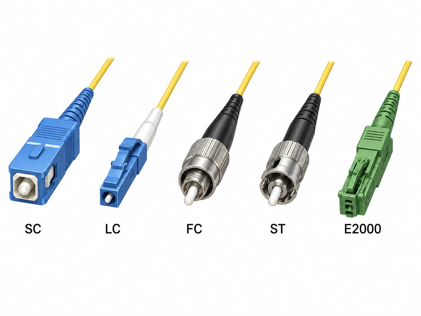
Connector choice is more mechanical than optical. LC dominates high-density panels because it doubles port count per rack unit, SC remains standard across GPON and much of the FTTH access layer, and FC persists in test and measurement and in older telecom frames. Before defaulting away from it, the threaded FC interface and where it still earns its place is worth checking. E2000 appears where a shuttered, high-return-loss interface is mandated. What matters on the spec line is naming the applicable IEC 61754 part along with the connector family, because that is what defines the mating geometry your panel and adapters were built to.
Spec Line 3: SC/APC vs SC/UPC Pigtail, and the Mistake That Damages Ferrules
A UPC end face is domed and mates flat against its counterpart. An APC end face is ground at 8°, which steers reflected light out of the core and into the cladding. The practical consequence is return loss. Angled interfaces are specified in the ≥60 dB region when mated and physical-contact interfaces around the ≥50–55 dB region, and the difference matters most where reflected power actively degrades the signal, which means PON and FTTx distribution, CATV overlays, DWDM and analog RF transport. For enterprise LAN, standard digital data links and most single-mode data center channels, a UPC fiber optic pigtail meeting a 50 dB return loss requirement is sufficient, provided the transceiver's own reflectance tolerance is checked rather than assumed.
An APC and a UPC connector must never be mated. The 8° face cannot achieve physical contact with a domed face, so the cores sit apart and return loss collapses, sending reflected power back toward the transmitter. Forcing the mate can also scratch or deform both contact surfaces, and a ferrule damaged this way may need replacement rather than cleaning.
Polish type is not a per-item field, it is a channel-wide field. The pigtail, the adapter, the patch panel port and the equipment interface all have to agree, and the RFQ should state the polish for every fiber optic pigtail and every adapter in the channel rather than assume the installer will notice. The interface geometry behind the angle is worked through in our breakdown of how APC connectors differ from UPC.
Spec Line 4: The Fiber Optic Pigtail Insertion Loss Standard Behind "IL ≤0.3 dB"
Insertion loss for a connector pair can be characterised two ways. Measured against a reference-grade master cord (a tuned, tightly controlled connector kept for metrology), a production connector produces a flattering figure. Measured as a random mate, where any connector from the batch is joined to any other, the distribution widens, because the two ferrules' core positions are no longer being compensated by an ideal partner. Both numbers are honest, and they are not the same number, which is why the fiber optic pigtail insertion loss standard you cite matters more than the digit you quote.
IEC 61753-1 resolves the ambiguity by defining attenuation grades statistically, on a random-mated basis, with the measurement method fixed as IEC 61300-3-34. Grade B is specified as a mean at or below 0.12 dB with 0.25 dB maximum for at least 97% of samples, Grade C at 0.50 dB maximum with a 0.25 dB mean, and Grade D at 1.0 dB maximum. A single sample passing at 0.3 dB against a reference cord is a far weaker statement than a batch meeting Grade B. Cite the standard with its current edition and amendment on the RFQ line, the same way you would cite any other acceptance document.
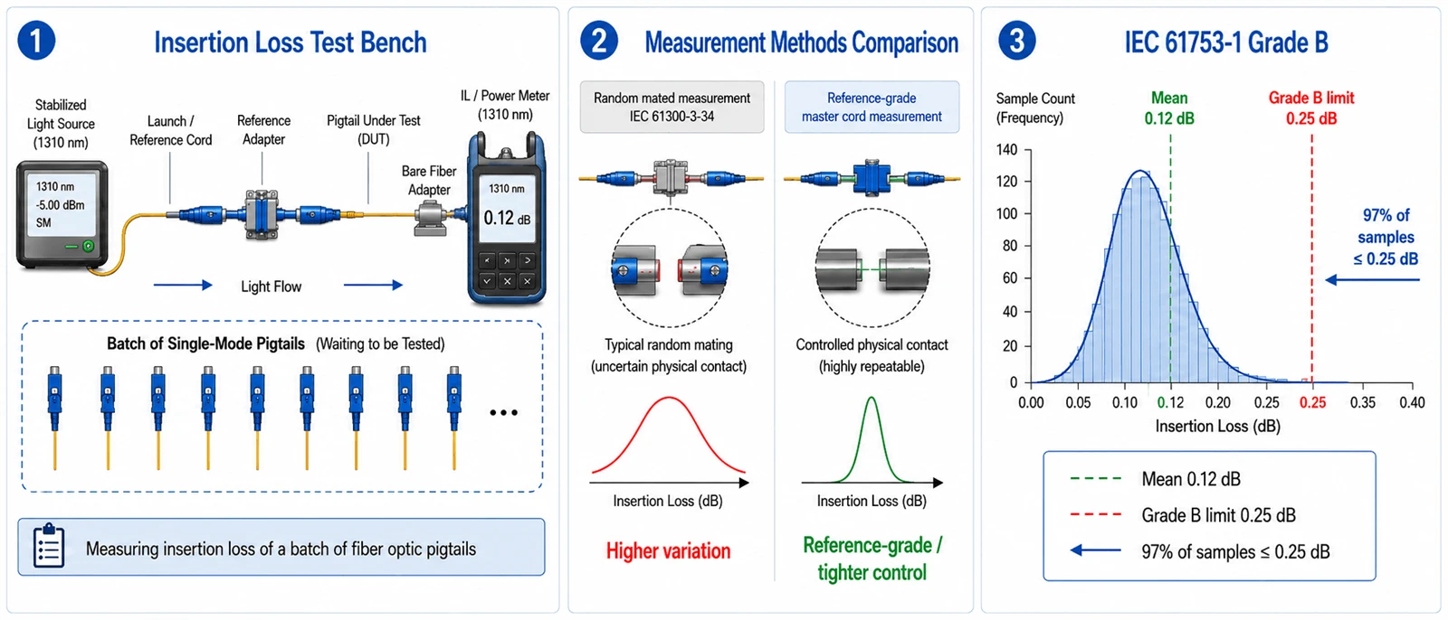
One distinction gets lost constantly, including in datasheets from suppliers who should know better. Attenuation grades and return loss grades are two parallel scales, not one. The letter grades B, C and D describe insertion loss. Return loss is specified separately, with the angled-interface level defined at ≥60 dB mated. Writing "Grade B" on an RFQ therefore says nothing at all about reflectance, and a fiber optic pigtail can meet Grade B while carrying whatever return loss the supplier chose to build. State both.
Grade B requires controlled core orientation
Achieving Grade B consistently commonly requires controlling where the fiber core sits relative to the ferrule axis, which in practice means the assembler orients and fixes the ferrule so core eccentricity falls in a known direction. A supplier without that step can produce a good sample. Producing a good distribution is a different capability, which is why the 2024 revisions to the IEC 61755-3 series formalised core-eccentricity statistics for these interfaces.
The adapter is part of the measured connection
The sleeve is what holds the two ferrules coaxial, so a loose-tolerance adapter can prevent the assembled connection from meeting the intended attenuation distribution even when the premium fiber optic pigtail itself is in grade. Verify as a mated connection rather than as a component. This is easy to miss precisely because incoming inspection usually tests the pigtail alone.
Spec Line 5: End-Face Inspection Criteria for a Fiber Optic Pigtail
Beneath the loss numbers sit the geometric parameters that produce them: radius of curvature, apex offset (how far the highest point of the dome sits from the fiber axis) and fiber height, the protrusion or undercut of the fiber relative to the ferrule. Together they determine whether the two cores actually touch under spring load. These are polishing process outputs, not design choices, which is why they are the fastest way to distinguish a controlled production line from a subcontracted one.
Cleanliness is the other half. End-face contamination is repeatedly identified across the industry as a leading cause of failure in installed fiber networks, and on a 9 µm single-mode core a particle sitting in the core region can cause severe attenuation or reflection rather than a marginal one. It also tends to show up as degraded return loss before it shows up as degraded insertion loss, so a power-meter reading can sit inside spec while a coherent or amplified system is already burning margin.
Optical performance governs, and visual inspection does not stand alone
The 2022 third edition of IEC 61300-3-35 states directly that visual inspection is in addition to, and does not replace, measurement of attenuation and return loss. It goes further: a connector that has been cleaned of loose debris and still fails visual inspection is not automatically rejected if it meets the specified optical performance (IEC). An RFQ clause reading "reject on visual failure" therefore contradicts the current standard. Write the acceptance rule the way the standard writes it, with inspection plus optical qualification and optical performance governing.
State the edition year, because the criteria moved
The third edition removed the inspection requirements for zones C and D and rewrote parts of the zone A and B criteria. "Complies with IEC 61300-3-35" without a date is therefore unenforceable, because supplier and buyer can grade against different rule sets and both be telling the truth (Fluke Networks).
Automate the grading, and treat packaging as part of the spec
Human pass/fail judgement varies with the technician, the ambient light and the display, which makes acceptance decisions non-reproducible, while automated image analysis produces a result that can be attached to a batch record. Packaging matters more than it looks: non-hermetic packaging is not a long-term cleanliness guarantee, so unopened should not be read as clean. Dust caps and packaging method belong on the fiber optic pigtail spec sheet, and field inspection before mating stays mandatory regardless of how good the factory data looks.
Spec Lines 6 to 8: 0.9 mm vs 2.0 mm Fiber Pigtail, Bunch Pigtail vs Ribbon Pigtail, and Length
Structure is chosen by the enclosure. The 0.9 mm tight-buffered construction is the default for splice-tray work because it routes and coils in confined trays, while 2.0 mm and 3.0 mm jacketed constructions add crush and tensile protection where the tail is handled repeatedly or leaves the enclosure. Heavier jackets are markedly harder to coil inside a tray built around a small minimum radius, which is the practical limit on how far up that scale you can go. Between the two splice methods there is a real decision: a 12-fiber bunch fiber optic pigtail splices individually, which suits mixed or phased terminations, while ribbon terminates by mass fusion, which is dramatically faster at scale but requires ribbon fiber on the incoming side and a matching splice protector regime. Ordering ribbon into a plant terminated for individual splicing converts a labour saving into a labour penalty.
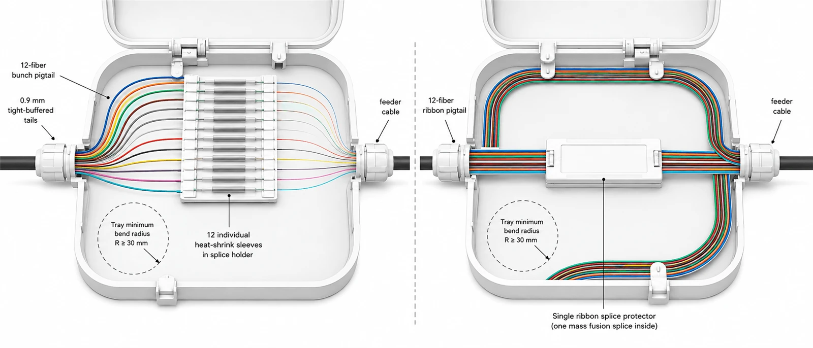
A 12 fiber pigtail color code may follow TIA-598 or the IEC convention depending on the project specification. Name the standard on the spec line rather than writing "standard colors", and verify it against the sequence already installed in the frame, because a frame populated under two conventions makes every future fault trace slower. That verification belongs at ODF acceptance and fiber management rather than at first fault.
Length is the field most often filled in from habit, and it is arithmetic rather than preference. Take the routing path from splice point to termination, add the slack the tray requires to coil at its specified minimum bend radius, add a service allowance, then round up to the next standard step. A worked illustration: a 1.2 m route, two coils in a tray whose stated minimum radius is 30 mm (roughly 0.19 m of fiber per turn, so 0.38 m), plus 0.1 m at the termination, gives 1.68 m, which becomes a 2.0 m order. Order below that and the fiber is forced past its bend limit, producing attenuation that appears only after the tray is closed. Order well above it and the excess congests the cassette, obstructing later work. The same arithmetic decides whether the enclosure itself has the capacity, which is the point at which patch panel and enclosure selection stops being a separate decision from the fiber optic pigtail specification.
Spec Line 9: Jacket Listing and Mechanical Limits for a Fiber Optic Pigtail
Jacket selection is driven by fire code before anything else. PVC is a commonly offered general-purpose material, an LSZH fiber optic pigtail is specified where smoke toxicity and opacity in enclosed occupied spaces are regulated, and OFNR and OFNP designations apply where riser and plenum listings are enforced. These are compliance decisions rather than performance ones. Write the listing your local building, electrical and fire code requires rather than a material name, because the requirement varies by jurisdiction and by project specification.
A standard indoor fiber optic pigtail is not built for direct outdoor exposure, and we would rather say so before an order than after. It lacks the UV-stable, weather-resistant jacketing and the reinforcement needed to survive temperature cycling, moisture ingress and mechanical stress. "Outdoor" is also not one condition, and armored and waterproof are not interchangeable answers. UV exposure drives jacket chemistry, standing water or condensation drives sealing and ingress protection, rodent and mechanical impact risk drives armoring, and the temperature range drives both material choice and the qualification the assembly has been tested to. Specify the conditions the assembly will see and let the construction follow.
Mechanical limits belong on the same line, as the assembly's own numbers. Pulling tension figures quoted for outside-plant trunk cable do not transfer to a short connectorized assembly, whose limiting parameters are the tensile rating of the tail cable and the connector retention force of the terminated end. Require both from the datasheet of the specific construction you are ordering, and require them for the SKU rather than for the product family.
Certification Claims: What GR-326 Covers, and What Almost Everyone Gets Wrong
Telcordia GR-326-CORE is the most cited and most misapplied credential in this product category. It sets out generic requirements for connectors used to join single-mode optical fibers and for the jumper assemblies made from them (Telcordia). Field-mountable connectors are covered separately under GR-1081, and connector cleaning products under GR-2923.
The document most often quoted alongside it is quoted wrongly. GR-1435-CORE is "Generic Requirements for Multi-Fiber Optical Connectors", which means multi-fibre, not multimode. It addresses multi-fiber connectors such as MPO-style assemblies, and its subject is still single-mode. A great deal of supplier literature transcribes it as the multimode counterpart to GR-326, and buyers inherit the error into their own RFQs. If a supplier offers GR-326 documentation to support a multimode fiber optic pigtail, the correct response is not to ask for GR-1435. It is to recognise that no Telcordia GR document in that family covers the product, and to specify acceptance on IEC performance grades and batch test data instead.
Qualification evidence and delivery evidence are not the same document
A GR-326 qualification report describes a connector design that survived a test regime; it says nothing about the reel arriving next month. ISO 9001 certifies that a manufacturing process is documented and controlled, not that any batch met an optical specification, and CE and RoHS are market-access and substance declarations. What describes your shipment is a test record tied to your batch, stating the measurement method, the wavelength, the sample basis and the batch identifier. Ask for third-party qualification when you are approving a connector design into a network standard. Ask for batch records when you are accepting delivery of a fiber optic pigtail order. Confusing the two is how buyers end up with an impressive certificate and an unverifiable reel.
Two Worked Examples: A Fiber Optic Pigtail for a GPON Cabinet and for a Data Center ODF
The same nine fields produce materially different optical and mechanical requirements depending on where the product lands. Both columns below are an illustrative starting specification derived from the assumptions stated, not a universal requirement.
The assumptions, and how they produce the grade. The GPON column assumes a class B+ PON budget of 28 dB, a 1:32 splitter consuming roughly 17.5 dB, around 5 dB of fiber and splice loss, and two mated connector pairs. That leaves several dB unallocated, so Grade C is sufficient and specifying Grade B buys margin the link does not need. The data center column assumes a channel budget near 2.6 dB at the intended rate and reach, roughly 1.0 dB of fiber and splice loss, 0.6 dB held as engineering margin, and four mated pairs sharing the remaining 1.0 dB. That allows 0.25 dB per pair as a mean, which Grade C would consume entirely with no headroom, while Grade B's 0.12 dB mean leaves room for ageing and re-mating. Change the split ratio, the pair count or the reserved margin and the grade recommendation changes with it. The grade is an output of the budget, not an attribute of the application.
| Spec field | GPON splitter cabinet, FTTH access | High-density data center ODF |
|---|---|---|
| Fiber type | G.657A2 (compact enclosure, tight coiling) | G.652D / OS2 |
| Connector | SC, IEC 61754-4 | LC, IEC 61754-20 |
| Polish | APC, channel-wide including adapters | UPC, channel-wide, RL requirement stated |
| Attenuation grade | Grade C, random mated per IEC 61300-3-34 | Grade B, random mated, oriented ferrules, matched adapters |
| Return loss | Stated separately from the grade | Stated separately from the grade |
| End-face | Automated grading, IEC 61300-3-35:2022, optical performance governing | Same, plus geometry report per batch |
| Structure | 0.9 mm tight buffer, single fiber | 0.9 mm, 12-fiber bunch or ribbon per splice method |
| Count / color | 1–12, color standard named | 12 / 24 / 48, color standard named |
| Length | Calculated from cassette routing and coil allowance (starting range 1.0–1.5 m) | Calculated from tray and rack path (starting range 1.5–2.0 m) |
| Jacket and limits | Listing per local code, conditions stated, tensile and retention per SKU | Listing per local code, tensile and retention per SKU |
On our side, the nine fields map to production steps that leave records: incoming fiber and ferrule verification, cleaving and cleaning, connector assembly with temperature-controlled curing, separate polishing programs for UPC and APC, automated end-face inspection, and optical testing for insertion loss, return loss, continuity, polarity, color sequence and length before final labelling. Which of those records is worth demanding depends on the deployment, and the practical differences between FTTH, ODF and data center environments decide whether you need per-item data or a batch statistic.
Your Fiber Optic Pigtail Spec Sheet Checklist
Write the nine lines. State the measurement method and the attenuation grade separately from the return loss requirement on line 4, state the edition year and the governing acceptance rule on line 5, make polish type a channel-wide statement rather than a per-item one, calculate length from the enclosure, and require tensile and retention figures for the SKU rather than for the family. That alone removes most of the delivery disputes this product category generates.
For the rest, ask for documents rather than assurances. Available with an order: datasheets, per-item or per-batch test records with the measurement method stated, insertion loss and return loss reports, packing lists and conformity certificates. You can request a sample tested against your own nine-line specification, with its batch test record. Send the nine fields and we will respond in the same format, including the lines we would push back on. Full specification options and customisation fields are listed on the fiber optic pigtail product page.
FAQ
Does "insertion loss ≤0.3 dB" on a fiber optic pigtail datasheet mean the same thing from every supplier?
No, it depends entirely on whether the figure was measured against a reference cord or as a random mate. The grade definitions, the measurement method and what to write instead are in Spec Line 4.
Can an APC fiber optic pigtail be mated to a UPC port?
No. The geometries cannot achieve physical contact, and forcing the mate can damage both end faces beyond cleaning. Why polish type has to match across the whole channel is covered in Spec Line 3.
Which fiber optic pigtail length should be specified?
The one calculated from the routing path plus the coil the tray requires at its own specified minimum bend radius, not a default value. The calculation is worked through in Spec Lines 6 to 8.
Is a Telcordia GR-326-CORE claim valid for a multimode fiber optic pigtail?
No, and GR-1435 is not the multimode alternative either, despite how often it is described that way. What to require instead is in Certification Claims.
Can a standard indoor fiber optic pigtail be installed outdoors?
No. Which construction replaces it depends on which outdoor condition dominates, and UV, water ingress, rodent and impact risk, and temperature range call for different answers. See Spec Line 9.