In an FBT splitter vs PLC splitter comparison, neither technology is automatically better for every fiber network. FBT is usually the first option to evaluate when a project needs a low port count, a defined wavelength window or an unequal split such as 10/90. PLC is generally the stronger choice for equal, high-density splitting, broad wavelength coverage and consistent output performance in FTTH and PON networks.
The decision should not be based on the technology name or unit price alone. Port count, split pattern, maximum insertion loss, uniformity, operating wavelengths, package type, connector loss and the complete optical budget all affect whether a splitter is suitable.
Readers who need a broader introduction can first review this guide to optical splitter types and working principles. The sections below focus specifically on how FBT and PLC designs differ and how to turn those differences into a defensible selection.
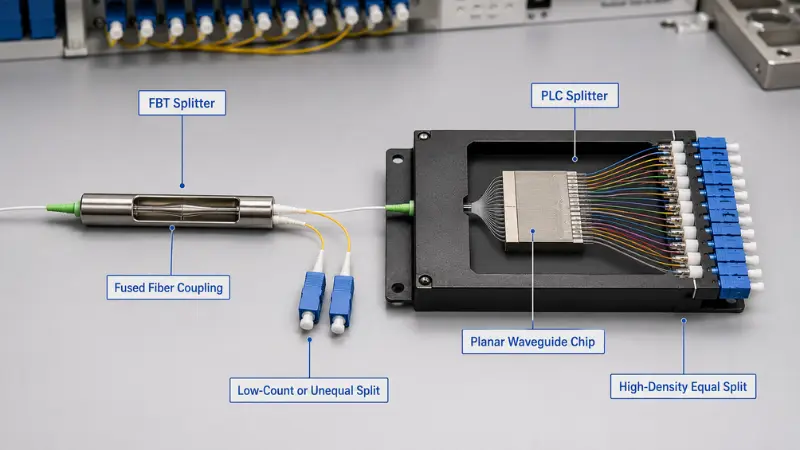
FBT or PLC: Quick Selection Guide
| Project Requirement | Technology to Evaluate First | Reason |
|---|---|---|
| Unequal split such as 5/95, 10/90 or 20/80 | FBT | FBT couplers are commonly designed for asymmetric optical power distribution. |
| Simple 1×2 split at a defined wavelength | FBT or PLC | Both may work; compare guaranteed loss, bandwidth, package and total installed cost. |
| Equal 1×8, 1×16, 1×32 or 1×64 distribution | PLC | PLC technology is well suited to compact, high-count and uniform equal splitting. |
| FTTH network supporting several PON wavelength plans | PLC | Broadband PLC products are commonly specified across a wide single-mode operating range. |
| Monitoring tap that must preserve most power on the through path | FBT | An asymmetric coupling ratio can reserve only a small percentage for monitoring. |
| Outdoor cabinet or closure | Qualified finished assembly | Outdoor suitability depends on packaging, sealing, pigtail protection and qualification, not PLC or FBT technology alone. |
| Lowest initial component price | Project-specific comparison | Connectorization, field splicing, enclosure space, test requirements and replacement labor can outweigh the bare component price. |
What Does an Optical Splitter Do?
An optical splitter is a passive component that distributes input optical power among two or more output fibers. It does not amplify, regenerate or electronically switch the signal. Every output therefore receives less optical power than the input, even when the device itself has no manufacturing loss.
Optical splitters are used in FTTH, GPON, XGS-PON, optical distribution networks, monitoring links and other point-to-multipoint systems. Configurations may be written as 1×2, 1×8 or 2×16, where the first number identifies the input count and the second identifies the output count.
The terms coupler and splitter sometimes overlap. A coupler may combine or divide optical power, while splitter is commonly used when the primary purpose is distribution to several outputs. For a more detailed explanation of the parameters shared by these devices, see this guide to fiber optic coupler and splitter specifications.
How FBT and PLC Splitters Work?

FBT Splitter Technology
FBT stands for Fused Biconical Taper. During manufacturing, two or more optical fibers are aligned, heated, fused and stretched to create a tapered coupling region. The manufacturing process controls how optical power transfers between the fibers.
Because the coupling can be adjusted, FBT devices are particularly useful for unequal ratios. Commercial products may be designed for 50/50, 40/60, 20/80, 10/90 or other specified distributions. AFL, for example, publishes fused wideband couplers with available coupling ratios from 5% to 50%. This is a product-family example rather than a universal specification for every FBT device. AFL's official wideband coupler information provides the corresponding scope and qualification details.
A compact 1×2 FBT fiber optic splitter may therefore be appropriate for a monitoring tap, low-count branch or application where two paths require different power levels.
FBT performance must still be evaluated from the actual data sheet. Some products are optimized for selected wavelength windows, while qualified wideband designs are also available. It is not accurate to assume that every FBT splitter has the same wavelength sensitivity, temperature range or port-count limitation.
PLC Splitter Technology
PLC stands for Planar Lightwave Circuit. A PLC splitter uses optical waveguides formed on a chip. An input fiber array and an output fiber array are precisely aligned with the chip, bonded and protected inside the final package.
This structure is well suited to equal power distribution across many outputs. A published AFL PLC splitter family, for example, specifies operation across 1260–1650 nm, even splitting across its stated bandwidth, low PDL and configurations extending from 1×4 to 2×32. Those figures apply to that product family and should not be treated as guarantees for every PLC splitter. AFL's PLC splitter specification also states that its listed insertion-loss values exclude connectors.
Buyers can review the available PLC splitter product range when matching port count, connector, pigtail and package requirements.
FBT Splitter vs PLC Splitter Comparison
| Comparison Factor | FBT Splitter | PLC Splitter |
|---|---|---|
| Optical structure | Fused and tapered optical fibers | Waveguide circuit with aligned input and output fiber arrays |
| Typical split pattern | Equal or unequal | Most commonly equal |
| Strongest application | Low-count branches and asymmetric taps | Equal, high-density distribution |
| Wavelength behavior | Depends strongly on the selected product design and wavelength window | Broadband products are commonly available for single-mode access networks |
| High output counts | May require several fused stages, increasing cumulative loss and assembly complexity | Well suited to compact high-port-count configurations |
| Port uniformity | Product-specific and more difficult to control across many cascaded outputs | Generally better suited to controlling uniformity across many equal outputs |
| Package size | Low-count devices can be compact; multiple stages may require more space | High output counts can be packaged in compact modules |
| Temperature and environmental performance | Depends on package and qualification | Depends on package and qualification |
| Cost tendency | May be economical for simple low-count or unequal designs | Often provides better value as equal port count and density increase |
| Common network use | Monitoring, tap architectures and selected low-count distribution | FTTH, GPON, XGS-PON and high-density ODN distribution |
The table describes design tendencies, not contractual limits. A low-quality PLC splitter can perform worse than a well-qualified FBT coupler. The technology label is not a substitute for a complete specification and test report.
Optical Parameters That Decide Performance
| Parameter | What It Means | How to Compare It |
|---|---|---|
| Maximum insertion loss | The highest permitted loss from the input to an output port | Use the guaranteed maximum value and confirm whether connectors are included. |
| Uniformity | The loss difference between the best and worst output ports | Use the maximum permitted variation, not only average output power. |
| PDL | Loss variation caused by changes in the state of polarization | Compare maximum PDL across the specified wavelength and temperature range. |
| Return loss | A measure of optical reflection returning toward the source | Higher return-loss values generally indicate lower reflection. |
| Directivity | Isolation between optical paths or output ports | Check the guaranteed minimum value and the applicable test conditions. |
| Wavelength-dependent loss | Variation in insertion loss across the operating wavelength range | Confirm the complete operating band rather than checking only one test wavelength. |
| Temperature-dependent loss | Change in insertion loss as the component temperature changes | Do not confuse a stated operating range with guaranteed optical stability across that range. |
| Connector loss | Additional loss introduced by factory-installed connectors and field mating | Confirm whether the splitter specification is for bare fiber, pigtails or a complete connectorized assembly. |
Insertion loss deserves particular attention. A published value may describe the bare splitter only, while another supplier may include factory-installed connectors. Those two values cannot be compared directly.
Connector polish also affects reflection and mating compatibility. SC/APC is common in access networks where reflection control is important, but the correct interface must match the equipment, adapter and existing plant. APC and UPC end faces should not be directly mated. This guide to PC, UPC and APC connector polish explains the mechanical and return-loss differences.
How Split Ratio Affects Optical Loss?
Even an ideal passive splitter must divide the available power. For an equal 1×N splitter, the theoretical splitting loss is:
Ideal splitting loss = 10 × log10(N)
| Equal Split | Approximate Ideal Loss |
|---|---|
| 1×2 | 3.0 dB |
| 1×4 | 6.0 dB |
| 1×8 | 9.0 dB |
| 1×16 | 12.0 dB |
| 1×32 | 15.1 dB |
| 1×64 | 18.1 dB |
These are mathematical minimums. Actual maximum insertion loss is higher because the manufactured device introduces excess loss, transition loss and, where applicable, connector loss.
Representative product options include a 1×2 PLC splitter, 1×8 PLC splitter, 1×16 PLC splitter, 1×32 PLC splitter and 1×64 PLC splitter. Their actual limits must be taken from the corresponding approved specification rather than from the theoretical table above.
Unequal FBT Split Loss
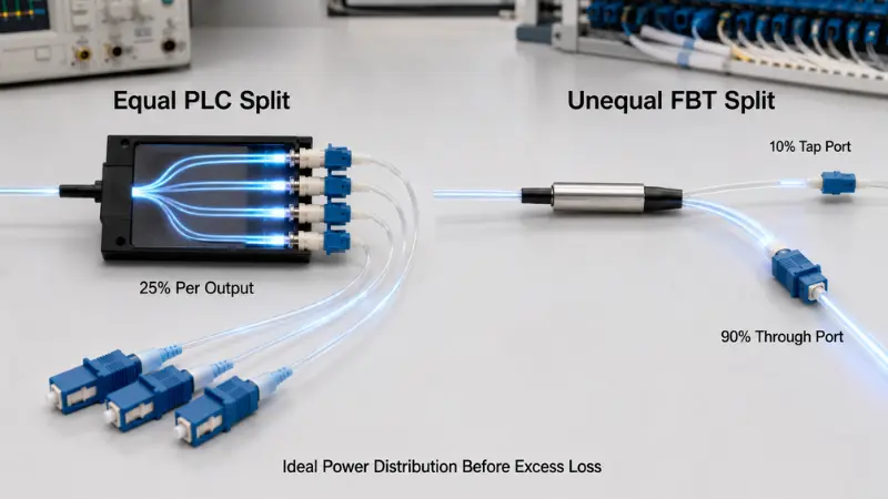
For an unequal branch receiving a fraction p of the input power, the ideal branch loss is:
Ideal branch loss = −10 × log10(p)
For a theoretical 10/90 split:
- The 10% branch has an ideal loss of 10.0 dB.
- The 90% branch has an ideal loss of approximately 0.46 dB.
The real insertion loss on both paths will be higher because the coupler has excess loss and a permitted coupling-ratio tolerance. The purchase specification should therefore identify the tap port, through port, coupling tolerance and maximum loss for each path.
This difference is why FBT remains relevant in long or branched access layouts. A more detailed application discussion is available in this guide to unbalanced splitting for rural FTTH projects.
Worked Example: A 1×32 PLC Optical Budget
The following is an illustrative calculation, not a universal PON design. Every value must be replaced with the actual cable, component and equipment specification for the project.

| Loss Item | Example Assumption | Calculated Allowance |
|---|---|---|
| Fiber attenuation | 10 km × 0.35 dB/km | 3.5 dB |
| Mated connector pairs | 4 × 0.5 dB | 2.0 dB |
| Fusion splices | 6 × 0.1 dB | 0.6 dB |
| 1×32 PLC splitter | 17.4 dB maximum, based on one published bare-splitter product family | 17.4 dB |
| Engineering and aging margin | Project assumption | 3.0 dB |
| Total path allowance | 26.5 dB |
The 17.4 dB splitter figure comes from one AFL PLC data sheet and explicitly excludes connectors. It is included only to demonstrate the calculation method.
If the selected OLT and ONT combination provides a verified 29 dB optical budget under the applicable operating conditions, this example leaves 2.5 dB after the stated engineering allowance. If the equipment budget is lower, the path is longer or additional connections are added, the design may fail.
A proper calculation should use:
- Maximum component loss rather than typical loss
- The longest planned optical path
- The worst splitter output port
- The correct wavelength-dependent fiber attenuation
- All connectors, adapters and splice points
- The actual OLT and ONT optical class
- An agreed engineering and aging margin
Centralized vs Cascaded Splitting
| Architecture | Advantages | Risks and Trade-Offs |
|---|---|---|
| Centralized splitting | One principal splitter stage, simpler loss accounting, easier port management and fewer passive stages | May require more distribution fiber and careful placement of the central splitter location |
| Cascaded splitting | Can place smaller split stages closer to subscriber groups and support distributed network layouts | Adds splitter stages, connection points, cumulative excess loss and troubleshooting complexity |
A 1×4 splitter followed by a 1×8 splitter creates an overall 1×32 split, but the path loss is not limited to the 15.1 dB ideal 1×32 division. The design must add the specified insertion loss of both splitter stages, together with the connections and splices between them.
CommScope documents low-count PLC modules in distributed split architectures where another splitter stage is installed farther into the outside plant. This demonstrates that low-count PLC products can also be used in cascaded designs; architecture should not be inferred from the technology name alone.
When an FBT Splitter Is the Better Fit?
FBT should be evaluated first when the required power distribution is unequal. Monitoring taps, staged rural branches and links with intentionally different branch budgets are stronger reasons to choose FBT than simply comparing its purchase price with PLC.
FBT can also be suitable for a low-count split at a clearly defined wavelength, especially where the project does not require broad multi-wavelength compatibility or future migration through the same passive path.
Before approval, verify:
- Designed wavelength window
- Coupling ratio and ratio tolerance
- Maximum insertion loss for each output
- Return loss and directivity
- Temperature-dependent performance
- Package, fiber protection and connector type
Do not reject every FBT device because it uses fused technology. Qualified wideband FBT products exist, and their performance should be judged from the specific data sheet and reliability evidence. Conversely, do not use a narrow-window FBT product in a network whose future wavelength requirements have not been defined.
When a PLC Splitter Is the Better Fit
PLC is generally the more practical choice when the project requires many equal outputs, compact packaging and controlled port-to-port uniformity. These conditions are common in FTTH distribution using 1×8, 1×16, 1×32 and 1×64 configurations.
PLC is also a stronger candidate when the same passive infrastructure must support several access-network wavelength plans. The physical-layer requirements for GPON and XGS-PON are defined in the applicable ITU-T G.984.2 GPON recommendation and ITU-T G.9807.1 XGS-PON recommendation. Designers should use the current equipment specifications and applicable recommendation rather than assuming that every network uses the same wavelength plan or optical budget.
PLC is not automatically an outdoor product. A steel tube, ABS module or cassette must still be protected within an enclosure appropriate to the installation. Reliability depends on the complete assembly, including pigtails, strain relief, connectors, adapters, sealing and environmental qualification.
Seven-Step Splitter Selection Process
- Define the power distribution:Specify equal or unequal outputs, input count, output count and any required tap or through port.
- List every current and planned wavelength:Include upstream, downstream, overlay and migration requirements.
- Select the split architecture:Compare centralized and cascaded designs, not only the final subscriber count.
- Calculate the worst-case optical budget:Use maximum losses, the longest route and the weakest splitter output.
- Define the installation environment:State indoor or outdoor use, temperature range, humidity, enclosure, handling and service-life expectations.
- Choose the package and connector:Match the module to the splice tray, terminal box, cabinet, ODF or rack.
- Review quality documentation:Request guaranteed specifications, test wavelengths, serialized reports and applicable qualification evidence.
For projects that include splitters, adapters, pigtails, terminal boxes and patch cords in the same bill of materials, the FTTH passive component procurement guide provides a broader purchasing framework.
Package and Connector Selection
| Package Type | Typical Installation | Main Benefit | Main Consideration |
|---|---|---|---|
| Bare fiber | Integrated module, protected splice tray or custom assembly | Smallest footprint | Requires controlled handling and complete external protection |
| Steel tube or blockless | Splice tray, closure or compact distribution box | Improved mechanical protection with a compact form | Fiber routing and bend radius remain critical |
| ABS module | Wall box, cabinet or protected outdoor distribution enclosure | Jacketed pigtails and stronger component protection | Uses more space than a bare or steel-tube device |
| LGX or plug-in cassette | Modular cabinet, ODF or distribution frame | Fast replacement, clear port identification and plug-and-play installation | Requires compatible chassis dimensions and adapter layout |
| Rack-mount splitter | Central office, equipment room or high-density rack | Organized front access and high port capacity | Consumes rack space and adds adapter connections |
This overview of PLC splitter package types can help match the optical component to its enclosure. A splitter intended for wall-mounted access distribution may also be integrated into a suitable enclosure such as a 24-core fiber distribution box, provided the tray capacity, adapter count, cable routing and sealing requirements match the project.
Connectorized splitters reduce field-splicing work and simplify replacement, but every mated pair adds loss and requires end-face inspection. Unterminated pigtails can reduce adapter points but require fusion-splicing equipment, trained installers and protected splice storage.
How to Compare Supplier Data Sheets?
| Item to Request | What the Supplier Should State | Risk if It Is Missing |
|---|---|---|
| Configuration | 1×N or 2×N, equal or unequal ratio, port identification | The supplied device may not match the network architecture. |
| Operating wavelength | Complete guaranteed wavelength range | Loss may be acceptable at one wavelength but not across the required service band. |
| Insertion loss | Maximum loss for every configuration and whether connectors are included | Supplier quotations cannot be compared on the same basis. |
| Uniformity | Maximum port-to-port loss variation | One subscriber branch may have significantly less margin than the others. |
| PDL | Maximum value and test conditions | Performance variation may be hidden behind an average insertion-loss figure. |
| Return loss and directivity | Guaranteed minimum values | Reflection and port isolation performance remain unknown. |
| Temperature performance | Operating range and permitted optical change across that range | A wide temperature label may not represent stable optical performance. |
| Package and fiber | Dimensions, fiber type, coating, jacket, pigtail length and bend requirements | The device may not fit the intended tray, box or rack. |
| Connector specification | Connector type, polish, grade and whether testing includes the connector | Unexpected loss or compatibility problems may occur during installation. |
| Test report | Test wavelengths, individual port results, serial number and test date | The delivered product cannot be traced to the reported measurements. |
GR-1209 and GR-1221 Claims
GR-1209 and GR-1221 are commonly referenced together when suppliers discuss passive optical component qualification and long-term reliability assurance. A claim such as "Telcordia compliant" should identify:
- The applicable standard and issue
- The tested product configuration
- The test laboratory
- The test scope and applicable sections
- Whether the result applies to the bare component or complete connectorized assembly
Incoming Inspection and Testing
- Confirm product identity:Check technology, configuration, ratio, wavelength, fiber, pigtail length, connector polish, serial number and label.
- Inspect the package and fibers:Look for crushed tubing, loose strain relief, sharp bends, damaged jackets, exposed fiber or incorrect port numbering.
- Inspect and clean connector end faces:Do not connect a contaminated splitter to the test set or live network.
- Set a reference and measure every output:Use a stable source and calibrated optical power meter at the specified test wavelengths. Record the loss of each port and calculate uniformity from the best and worst results.
- Compare results with contractual limits:Do not use a generic internet table as the pass or fail standard.
- Retain traceable records:Store the purchase order, batch, serial number, test wavelength, test equipment identification, operator and inspection date.
A normal receiving check using a source and power meter can verify insertion loss and uniformity. Independent PDL, return-loss or environmental verification may require dedicated equipment, a qualified laboratory or supplier qualification records.
Five Common Selection Mistakes
- Choosing only by unit price:A cheaper bare component may require more field splicing, enclosure space, labor and troubleshooting.
- Comparing typical loss with maximum loss:A typical value describes expected performance; a maximum value defines the contractual limit. They are not interchangeable.
- Ignoring connector inclusion: A bare splitter specification cannot be compared directly with a connectorized module unless the measurement boundaries are the same.
- Assuming every PLC splitter is superior:Chip quality, fiber-array alignment, packaging, connectors and testing determine the finished result.
- Forgetting future wavelengths and architecture changes:A splitter that works for the present service may restrict a later PON migration or overlay.
RFQ Specification Template
The following block can be adapted for a supplier inquiry:
Required technology: FBT / PLC / supplier recommendation
Input and output configuration: 1×__ / 2×__
Split pattern: equal / unequal __% / __%
Operating wavelength range: __
Maximum insertion loss: __ dB, connectors included / excluded
Maximum uniformity: __ dB
Maximum PDL: __ dB
Minimum return loss: __ dB
Minimum directivity: __ dB
Package type and dimensions: __
Fiber type and pigtail length: __
Connector type and polish: __
Operating and storage temperature: __
Installation environment: indoor / outdoor enclosure / closure / rack
Required test report: individual / batch
Required reliability or qualification evidence: __
Required labeling and serial-number traceability: __
Frequently Asked Questions
Q: Which Is Better, FBT Or PLC?
A: FBT is usually the better starting point for low-count or unequal power distribution. PLC is generally the better starting point for equal, high-density splitting across a broad stated wavelength range. The final answer depends on the guaranteed product specification and complete optical budget.
Q: Is PLC Always Lower Loss Than FBT?
A: No. The unavoidable theoretical loss is determined by how the optical power is divided. PLC usually offers stronger uniformity and packaging efficiency for many equal outputs, but actual insertion loss must be compared using maximum values under the same test conditions.
Q: Does A 1×32 Splitter Only Add 15.1 DB?
A: No. Approximately 15.1 dB is the ideal mathematical loss of dividing power equally among 32 outputs. The actual splitter adds excess loss, and the complete path may also include connectors, adapters, splices, fiber attenuation and engineering margin.
Q: Can FBT Splitters Be Used In PON Networks?
A: They can be used when their split ratio, wavelength range, insertion loss, environmental performance and architecture fit the network. PLC is more common for high-count equal FTTH splitting, but FBT may serve low-count or asymmetric branches.
Q: Can PLC Splitters Be Cascaded?
A: Yes. PLC splitters can be used in centralized or cascaded layouts. Every stage must be included separately in the optical budget, and the additional connection points should be considered in maintenance and fault isolation.
Q: Should I Choose A Connectorized Or Splice-Ready Splitter?
A: Choose a connectorized module when rapid installation, replacement and port access are priorities. Choose a splice-ready device when reducing adapter points and integrating the splitter into a protected splice tray are more important.
Conclusion
The FBT splitter vs PLC splitter decision begins with the required power distribution. An unequal monitoring tap or simple low-count branch often points toward FBT. Equal high-density FTTH distribution, broad wavelength compatibility and controlled port uniformity generally point toward PLC.
Technology selection is only the first step. A reliable decision also requires maximum insertion loss, uniformity, wavelength coverage, environmental limits, package, connector, test documentation and a complete worst-case optical budget.
Providing those requirements in the RFQ reduces quotation ambiguity and supports a more reliable network design. Project buyers can submit the splitter specification for technical and quotation review once the required ratio, package, connector and operating conditions have been defined.