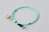
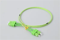
How far can a fiber optic cable actually run? That depends on more than the cable itself. Fiber type, data rate, transceiver standard, wavelength, connector loss, splice loss and link budget all play a role. A 10G SR link over OM3 multimode fiber tops out around 300 meters, while a 10G LR link over OS2 single-mode fiber can reach 10 km with the same speed. The cable is only one variable in the equation.
As a working rule, multimode fiber handles shorter links inside data centers, buildings and campuses, while single-mode fiber covers longer runs for backbones, metro networks and telecom. But to plan a real link, you need to match the fiber cable with the correct optical transceiver and calculate the full loss budget.

How Far Can Fiber Optic Cable Run?
Fiber optic cable can run from a few meters to well over 80 kilometers, depending on the network design. Short data center links on multimode fiber may cover tens or hundreds of meters. Enterprise or campus backbones on OM3 or OM4 multimode fiber work well for many 10G, 40G or 100G applications within their rated distances. For long-haul links, OS2 single-mode fiber with the right optics supports 10 km, 40 km, 80 km or more.
There is no universal maximum fiber optic cable distance. The maximum is determined by the complete link - not the cable alone.
Consider two common 10G scenarios. A Cisco 10GBASE-SR transceiver over OM3 multimode fiber supports up to 300 m, or up to 400 m over OM4. A 10GBASE-LR transceiver over standard single-mode fiber supports 10 km. Same speed, very different reach - because the transceiver and fiber type define the limit together.
What Determines Fiber Optic Cable Distance?

Fiber Type: Single-Mode vs Multimode
Single-mode fiber has a small core - typically around 9 µm - and carries one main propagation mode. Because it avoids modal dispersion, it supports higher bandwidth over longer distances. The Fiber Optic Association (FOA) explains in its training material that single-mode fiber does not suffer from the modal dispersion that limits multimode fiber's reach.

Multimode fiber has a larger core, usually 50/125 µm or 62.5/125 µm. It allows multiple light paths, which makes it practical and cost-effective for short-reach links. But those multiple modes spread out over distance - a phenomenon called modal dispersion - and this limits both bandwidth and reach, especially at higher speeds. For a deeper comparison, see our single-mode vs multimode fiber guide.
Data Rate and Bandwidth
As speed increases, supported distance usually decreases. A fiber link that works at 1G over 550 meters of OM3 may only reach 300 meters at 10G, and just 70–100 meters at 100G with SR4 optics. This relationship is fundamental: never choose fiber only by its physical length without checking the target data rate.
In practice, an engineer upgrading a campus backbone from 10G to 100G will often find that existing OM3 runs of 200–300 meters no longer qualify. Either the fiber grade needs upgrading, or the transceiver standard must change to a single-mode option like 100GBASE-DR or 100GBASE-LR.
Transceiver Type and Wavelength
The optical module often determines the practical distance more than the cable itself. SR (short-reach), LR (long-reach), DR, FR, ER and ZR optics are each designed for different reach envelopes.
For example, a 100GBASE-SR4 transceiver is a short-reach multimode solution that supports up to 70 m over OM3 and 100 m over OM4 using MPO connectors. A 100GBASE-LR module over single-mode fiber supports 10 km. ER and ZR class optics extend to 40 km and 80 km respectively. The transceiver datasheet is always the authoritative source for distance ratings.
Connector, Splice and Patch Panel Loss
Every connector, adapter, splice and patch panel adds insertion loss. The longer and more complex the channel, the more these losses accumulate.
A short link with many patch panels can fail even when the cable length is within the nominal maximum distance. Meanwhile, a longer link with clean connectors, low-loss fusion splices and proper testing may perform reliably. According to the ANSI/TIA-568.3 standard, connector loss budgets should account for up to 0.75 dB per mated pair, though well-made factory patchcords typically come in well under 0.3 dB.
Link Budget and Receiver Sensitivity
A fiber link works only if enough optical power reaches the receiver. The link budget is the difference between the transmitter output power and the minimum receiver sensitivity. A simplified formula:
Available link margin = Transceiver power budget − fiber attenuation − connector loss − splice loss − safety margin
For a 10GBASE-SR link, the typical optical budget is around 6.1 dB. If a 300-meter OM3 run introduces roughly 1.05 dB of fiber attenuation (at 3.5 dB/km) and you have two mated connector pairs adding 0.6 dB total, plus a 1 dB safety margin, your remaining margin is about 3.45 dB - comfortable. Add two more patch panels (another 0.6 dB each) and the margin gets tighter. This is why calculating the link budget matters, especially on longer or more complex runs.
Installation Quality and Bend Radius
Poor installation can shorten the practical distance of any fiber link. Tight bends, dirty connector end faces, excessive pulling tension, poor splicing and mismatched connectors all increase loss. Always inspect and clean connectors before mating, follow the manufacturer's minimum bend radius requirements, and test the installed link with an optical loss test set. For installation best practices, see our fiber optic cable installation guide.
Single-Mode Fiber Distance
Single-mode fiber is the standard choice for long-distance and high-bandwidth links. It serves telecom networks, FTTH deployments, campus backbones, metro rings, data center interconnects and enterprise backbone cabling.
Why Single-Mode Fiber Supports Longer Distances
Single-mode fiber carries one main propagation mode through its 9 µm core, which eliminates modal dispersion entirely. It is typically optimized for 1310 nm and 1550 nm wavelengths. At 1310 nm, OS2 single-mode fiber has a rated attenuation of about 0.35 dB/km, and at 1550 nm it drops to around 0.22 dB/km. Compare that with multimode fiber's 3.5 dB/km at 850 nm - roughly ten times higher loss per kilometer. This fundamental difference in attenuation is why single-mode fiber dominates for anything beyond short-reach applications.
Common Single-Mode Fiber Distance Examples

The following table shows typical single-mode Ethernet optics and their common reach over OS2 fiber. These figures are based on standard transceiver specifications from IEEE 802.3 Ethernet standards and vendor datasheets.
| Application | Typical Fiber | Common Reach |
|---|---|---|
| 1000BASE-LX | OS2 single-mode | 10 km |
| 10GBASE-LR | OS2 single-mode | 10 km |
| 10GBASE-ER | OS2 single-mode | 40 km |
| 100GBASE-DR | OS2 single-mode | 500 m |
| 100GBASE-FR | OS2 single-mode | 2 km |
| 100GBASE-LR | OS2 single-mode | 10 km |
| 100G ER/ZR class optics | OS2 single-mode | 40–80 km |
| 400GBASE-DR4 | OS2 single-mode | 500 m |
| 400GBASE-FR4 | OS2 single-mode | 2 km |
Always confirm the exact distance in the transceiver datasheet for your specific deployment. These are planning references, not guaranteed limits for every installation.
Can Single-Mode Fiber Be Used for Short Distances?
Yes. Many modern data centers install single-mode infrastructure even for short or medium links to simplify future upgrades. A single-mode backbone can migrate from 10G to 100G to 400G by swapping transceivers - no recabling required.
However, for very short single-mode links with high-power optics, the receiver may overload. Some transceiver datasheets specify a minimum link length or require an optical attenuator for links shorter than a certain distance. For example, some 10GBASE-ER modules require a 5 dB attenuator for links under 20 km.
Multimode Fiber Distance
Multimode fiber is widely used for short-reach connections in data centers, enterprise buildings, equipment rooms and campus environments where runs stay within a few hundred meters.
Why Multimode Fiber Is Shorter-Reach
Because multimode fiber allows multiple light paths through its larger 50 µm core, signals spread out over distance. This modal dispersion limits both bandwidth and reach, and the effect gets worse at higher speeds. The OM fiber grades (OM1 through OM5) represent increasing levels of modal bandwidth, which is why higher-grade multimode fiber supports longer distances at faster data rates.
OM1, OM2, OM3, OM4 and OM5 Overview
| Fiber Type | Core Size | Common Jacket Color | Typical Use |
|---|---|---|---|
| OM1 | 62.5/125 µm | Orange | Legacy multimode networks (largely phased out) |
| OM2 | 50/125 µm | Orange | Legacy 1G and some short 10G links |
| OM3 | 50/125 µm | Aqua | 10G, short-reach 40G/100G data center links |
| OM4 | 50/125 µm | Aqua or violet (erika violet) | Higher-performance data center links, 10G/40G/100G |
| OM5 | 50/125 µm | Lime green | SWDM and selected wideband multimode applications |
OM3 fiber has a modal bandwidth of 2000 MHz·km at 850 nm, while OM4 reaches 4700 MHz·km at the same wavelength. This bandwidth difference directly translates into reach: at 10G, OM3 supports 300 m where OM4 supports 400 m. The TIA standardized OM4 fiber specifications through ANSI/TIA-568.3, and the Ethernet Alliance confirmed the 400-meter 10GbE distance for OM4 when IEEE incorporated it into the 802.3 standard.
Common Multimode Fiber Distance Examples

Multimode OM3 and OM4 fiber distance comparison for 10G 40G and 100G links
| Speed / Optic Type | OM3 | OM4 | Notes |
|---|---|---|---|
| 10GBASE-SR | Up to 300 m | Up to 400 m | Duplex LC, 850 nm, IEEE 802.3ae |
| 25GBASE-SR | Up to 70 m | Up to 100 m | Duplex LC, 850 nm |
| 40GBASE-SR4 | Up to 100 m | Up to 150 m | MPO/MTP parallel, 850 nm |
| 40G BiDi | 100 m | 150 m | Duplex LC, depends on transceiver |
| 100GBASE-SR4 | Up to 70 m | Up to 100 m | MPO/MTP parallel, 850 nm |
| 100G BiDi / SR1.2 | 70 m | 100 m | Some modules support extended OM5 reach |
These distances assume clean connectors, proper installation and standard link loss budgets. In a real deployment, connector contamination, extra patch points or tight bends can reduce the usable distance below these nominal values.
Does OM5 Always Go Farther Than OM4?
Not necessarily. OM5 was designed to support short wavelength division multiplexing (SWDM) by providing specified bandwidth at additional wavelengths beyond 850 nm (specifically 883 nm and 953 nm). In standard SR applications that only use 850 nm, OM5 may not offer a meaningful distance advantage over OM4. The benefit of OM5 appears primarily when the transceiver is designed to use SWDM capabilities - for example, certain 100G and 400G SWDM modules that reduce fiber count by transmitting on multiple wavelengths.
Fiber Optic Cable Distance Chart by Application
The following table provides a practical planning reference for common deployment scenarios. It is not a substitute for a proper link budget calculation, but it helps narrow down the right fiber type and connector for each situation.
| Scenario | Recommended Fiber | Common Connector | Typical Distance Range |
|---|---|---|---|
| Server to switch, same rack | DAC, AOC, OM3/OM4 or OS2 | SFP/QSFP direct attach, LC | 1–7 m (DAC), up to 30 m (AOC) |
| Data center row or room link | OM3/OM4 or OS2 | LC or MPO/MTP | 10–400 m |
| 10G enterprise backbone | OM3/OM4 or OS2 | LC duplex | 100 m to 10 km |
| 40G/100G short-reach data center | OM3/OM4 with MPO/MTP or duplex BiDi | MPO/MTP or LC | 70–150 m |
| Campus backbone | OS2 single-mode | LC | 1–10 km+ |
| Telecom / FTTH / metro link | OS2 single-mode | SC, LC or hardened connector | 10–80 km+ |
Single-Mode vs Multimode Fiber Distance: How to Decide
When Multimode Fiber Makes Sense
Multimode is a strong choice when the link stays inside a data center, building or equipment room and the distance is short enough for SR optics. If existing infrastructure is already OM3 or OM4 and the current speed requirement fits within the multimode distance limits, there is no immediate reason to replace it. Multimode transceivers (SR class) are typically less expensive per port than single-mode optics, and the fiber itself costs less per meter to terminate.
A typical scenario: a data center with top-of-rack switches connected to end-of-row aggregation switches over runs of 20–50 meters. OM4 fiber with 10G or 25G SR optics handles this easily, and the cost per link is significantly lower than a single-mode alternative.
When Single-Mode Fiber Is the Better Choice
Single-mode makes sense when the link exceeds multimode reach, when you need a future-proof backbone for 100G or 400G upgrades, or when building campus, metro, FTTH or telecom infrastructure. The cable cost difference between OS2 single-mode and OM4 multimode is modest, and single-mode transceivers have dropped in price considerably. For any new backbone installation where cabling will remain in place for 10–15 years, single-mode is usually the safer long-term investment.
A common deployment pattern: a campus network connecting six buildings over distances of 500 m to 3 km. OS2 single-mode trunk cables with LC patch cords at each end provide a backbone that starts at 10G and can migrate to 100G or 400G by swapping modules - without touching the cable plant.
For Data Centers
OM3 and OM4 remain the default for short-reach links, especially with SR optics. However, many new high-density data center designs are adopting OS2 single-mode for spine-leaf architectures to support 400G migration paths. The shift is particularly visible in hyperscale environments where 400GBASE-DR4 and 400GBASE-FR4 over single-mode fiber are becoming standard.
For Enterprise Buildings and Campus Networks
Within a single building, OM3 or OM4 may be sufficient if runs stay under 300 meters and 10G meets the current and near-term speed requirement. For building-to-building links or campus backbones, OS2 single-mode is usually the safer choice because it accommodates longer runs and higher speeds without recabling.
For Telecom and FTTH
Single-mode fiber is the only practical option for telecom and FTTH networks. These applications require low attenuation over long distances, high scalability and support for technologies like GPON, XGS-PON and 50G-PON. The infrastructure often uses PLC splitters and fiber terminal boxes alongside single-mode trunk cables.
How to Choose the Right Fiber Optic Cable for Your Distance
Step 1: Measure the Real Route Length
Do not measure only the straight-line distance between two devices. Include cable routing through trays, cabinets, patch panels, wall outlets, risers and service loops. In many buildings, the actual cable path is 20–40% longer than the floor-plan distance. Add a reasonable margin - typically 10% - for future rerouting and maintenance slack.
Step 2: Confirm Current and Future Speed Requirements
A cable that supports 10G today may not support 100G at the same distance tomorrow. Ask three questions before choosing fiber: What speed do I need now? What speed will I need in three to five years? Will this cable plant be reused for future upgrades? If the answer to the third question is yes, lean toward OS2 single-mode or at minimum OM4 for multimode runs.
Step 3: Match the Transceiver Standard
Check whether your equipment uses SR, LR, DR, FR, ER, ZR, BiDi, CWDM, PSM or another optical standard. The same fiber cable supports different distances with different modules. For example, an OS2 single-mode run of 2 km works for 100GBASE-FR (rated to 2 km) but is far short of the 100GBASE-LR limit (10 km) - both use OS2, but the transceiver determines the practical reach and cost.
Step 4: Calculate the Link Budget

Add up all expected losses in the channel:
Fiber attenuation: approximately 3.5 dB/km for multimode at 850 nm, or 0.35 dB/km for single-mode at 1310 nm. Connector loss: typically 0.2–0.5 dB per mated pair for LC or SC connectors. Splice loss: typically 0.1 dB or less for a good fusion splice. Patch panel and adapter loss: each additional connection point adds loss. Engineering safety margin: usually 1–3 dB depending on the application.
Then compare the total loss with the transceiver's specified optical budget. If the margin is thin, reduce connector count, upgrade fiber grade, or choose a transceiver with a larger power budget.
Step 5: Leave Margin
Do not design right at the maximum distance. Connector end faces degrade over repeated mating cycles, dust accumulates, and future patching may add connection points. A link that passes commissioning with 0.5 dB of margin is a link waiting to fail after the next maintenance window. Aim for at least 2–3 dB of headroom on critical backbone links.
Common Mistakes When Planning Fiber Optic Cable Distance

Choosing Fiber Only by Jacket Color
Jacket color is helpful for quick identification - aqua usually means OM3 or OM4, yellow usually means OS2, lime green usually means OM5. But "usually" is not "always." Some manufacturers use non-standard colors, and legacy cables may not follow current conventions. Always verify the printed cable rating, fiber type marking and test documentation before assuming a fiber grade based on color.
Ignoring Connector and Patch Panel Loss
A link with six mated connector pairs may exceed the loss budget even on a 50-meter cable run. Each additional cross-connect or patch panel adds loss. In high-density environments with multiple patch panels between the switch port and the end device, these losses stack up quickly. Plan the number of connection points at design time, not after installation.
Treating Maximum Distance as Recommended Distance
Maximum distance figures from transceiver datasheets assume clean connectors, no extra splices, factory-grade fiber and specific environmental conditions. Real installations rarely match those assumptions. Always treat the stated maximum as an upper boundary, not a design target.
Mixing Incompatible Connectors or Polarity
MPO/MTP links require correct polarity, fiber count and connector gender. A physically connected link may still fail or show high bit error rates if the polarity is wrong. The TIA-568.3 standard defines multiple polarity methods (Type A, Type B, Type C and the newer Type U variants), and mixing them incorrectly is one of the most common causes of failed 40G and 100G parallel optic links.
Forgetting Future Speed Upgrades
If you are installing backbone cabling that will stay in place for a decade, think beyond the current switch speed. Pulling new fiber through existing pathways is expensive and disruptive. Choosing OM4 instead of OM3, or OS2 instead of multimode, costs marginally more at installation but can save significant recabling expense later. Many organizations that installed OM3 for 10G now face costly upgrades as they move to 100G, where OM3 reach drops to just 70 meters with SR4 optics.
FAQ About Fiber Optic Cable Distance
Q: How Far Can Single-Mode Fiber Optic Cable Run?
A: Single-mode fiber supports anything from short links to distances exceeding 80 km, depending on the transceiver. Common Ethernet reaches include 10 km (LR class), 40 km (ER class) and 80 km (ZR class). With optical amplifiers, single-mode fiber can span hundreds of kilometers in telecom backbone applications.
Q: How Far Can Multimode Fiber Optic Cable Run?
A: Multimode fiber typically covers a few dozen meters to several hundred meters, depending on fiber grade and speed. At 10G, OM3 reaches 300 m and OM4 reaches 400 m. At 100G with SR4 optics, distances drop to 70 m (OM3) or 100 m (OM4). Older 1G applications can run farther - up to 550 m on OM3 - because the lower data rate is less sensitive to modal dispersion.
Q: What Is The Maximum Distance For 10G Fiber?
A: For 10G SR multimode links, OM3 supports up to 300 m and OM4 up to 400 m per the IEEE 802.3ae standard. For 10G LR single-mode links, 10 km is the standard reach. 10GBASE-ER extends to 40 km, and 10GBASE-ZR (vendor-defined, not IEEE-standardized) can reach 80 km with appropriate optics.
Q: Is OM4 Better Than OM3 For Distance?
A: Yes. OM4 generally supports longer multimode reach than OM3 because of its higher modal bandwidth (4700 MHz·km vs 2000 MHz·km at 850 nm). At 10G, the difference is 300 m vs 400 m. At 40G SR4, it is 100 m vs 150 m. For a detailed comparison, see our OM3 vs OM4 comparison.
Q: Can I Connect Single-Mode Fiber To Multimode Fiber Directly?
A: This is not recommended and will not work reliably in most cases. Single-mode fiber has a 9 µm core while multimode fiber has a 50 µm or 62.5 µm core. Coupling light from a larger core into a smaller one causes severe signal loss, and the mismatch in numerical aperture causes additional problems. Use the correct fiber type end to end, and use media converters or mode-conditioning patch cords only where specifically supported by the transceiver vendor.
Q: Does A Longer Fiber Cable Always Mean More Signal Loss?
A: Yes, fiber attenuation increases linearly with distance. But distance is only one component of total channel loss. Connectors, splices, bends and patch panels often contribute more loss per point than several hundred meters of fiber. A 100-meter link with four mated connector pairs can have higher total loss than a 500-meter link with just two connectors and a clean splice.
Q: What Fiber Should I Choose For 100G?
A: For short-reach 100G links under 100 meters, OM3 or OM4 multimode with SR4 or BiDi optics works well. For 500 m, use 100GBASE-DR over OS2 single-mode. For 2 km, 100GBASE-FR. For 10 km, 100GBASE-LR. For 40 km or more, ER or ZR class optics over OS2 single-mode are required.
Q: How Do I Calculate A Fiber Link Budget?
A: Start with the transceiver's specified power budget (transmitter output minus minimum receiver sensitivity). Then subtract: fiber attenuation (length × attenuation coefficient), connector loss (number of mated pairs × loss per pair), splice loss, and a safety margin. If the result is positive, the link should work. If it is near zero or negative, you need to reduce losses or choose a transceiver with a higher power budget.
Q: What Happens If A Fiber Link Exceeds The Transceiver's Rated Distance?
A: The link may experience increased bit error rate, intermittent connectivity or complete failure. Even if the link appears to work initially, it may lack sufficient margin to handle connector aging, temperature variation or additional patching. Operating beyond the rated distance voids the transceiver's performance guarantee and is generally considered an unsupported configuration.
Q: Is OM5 Worth It For Data Center Cabling?
A: OM5 is worth considering if you plan to deploy SWDM-based transceivers that use multiple wavelengths to increase capacity over multimode fiber. For standard SR applications at 850 nm, OM5 does not offer a significant distance advantage over OM4. The decision depends on whether your specific transceiver roadmap includes SWDM modules.
Conclusion
Fiber optic cable distance depends on the full link - fiber type, transceiver standard, data rate, connector count and total channel loss all matter. There is no single answer to "how far can fiber run" without knowing these variables.
For short data center or building links, OM3 and OM4 multimode fiber paired with SR-class optics remain practical and cost-effective. For campus backbones, telecom, FTTH and any deployment where future speed upgrades are expected, OS2 single-mode fiber is the stronger long-term choice.
Before purchasing fiber patch cables, trunk cables or transceivers, confirm the actual route distance, required speed, transceiver standard, connector type and fiber grade together. Then calculate the link budget. That process - not any single specification - is what ensures a stable, upgrade-ready network.