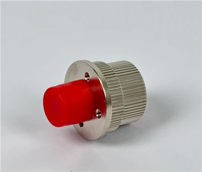
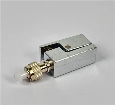
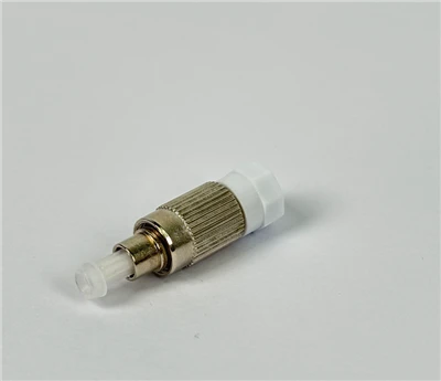
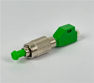
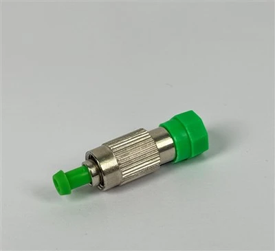
A fiber optic fast connector lets installers terminate optical fiber directly in the field - at a patch panel, an FTTH terminal box, an optical distribution frame, or a drop point - without waiting for factory-made cable assemblies. You may also see it called a fiber optic quick connector, a field-installable fiber connector, or a field assembly connector.
For most FTTH and access network projects, the real question is not just what a fast connector is, but which field termination method to use: a mechanical splice fast connector or a fusion splice-on connector. The answer depends on your link loss budget, cable type, installation environment, available tools, and whether the connection is temporary or permanent.
This guide walks through both methods in detail - how they work, where each one performs best, and what to watch for during installation - so you can choose the right fiber optic fast connector for your project.

What Is a Fiber Optic Fast Connector?
A fiber optic fast connector is a connector designed for on-site installation. Instead of ordering a pre-terminated patch cord or polishing a bare ferrule by hand, the installer strips the cable, cleaves the fiber, and either inserts it into a mechanical alignment structure or fusion-splices it to a factory-polished connector stub. The result is a field-terminated connector ready for testing and service.

Typical applications include:
- FTTH drop cable termination at subscriber wall outlets, terminal boxes, or indoor distribution points
- Fiber distribution in optical distribution frames (ODF) and patch panels
- Emergency fiber restoration when a pre-made assembly is not available on site
- Temporary links during construction, testing, or network commissioning
- Indoor cabling and last-mile access network projects
Most field-installable connector solutions fall into two categories: mechanical splice fast connectors and fusion splice-on connectors. Both produce a usable optical connection, but they differ significantly in loss performance, long-term reliability, tool requirements, and cost.
Is a Fusion Splice-On Connector Still a "Fast Connector"?
Strictly speaking, many installers use the term "fast connector" to refer to mechanical splice connectors - the kind you can install with a cleaver, a few hand tools, and no fusion splicer. However, fusion splice-on connectors are also a field termination solution, and they serve the same purpose: creating a connectorized fiber end on site without factory polishing.
In this guide, we treat both as field-installable connector options and compare them side by side so you can decide based on your actual project requirements rather than terminology.
Mechanical Fiber Optic Fast Connector: How It Works
A mechanical splice fast connector contains a short, factory-polished fiber stub pre-mounted inside the connector ferrule. In the field, the installer aligns a stripped and cleaved fiber to this stub using a precision V-groove or similar alignment mechanism. Index-matching gel between the two fiber ends reduces Fresnel reflection and helps minimize optical loss at the junction.

The installation sequence is straightforward: strip the cable jacket and coating to the manufacturer's specified length, clean the bare fiber, cleave it, slide it into the connector body until it meets the pre-polished stub, and lock the mechanism in place.
Mechanical fast connectors are available in common interface types, including SC APC, SC UPC, and LC configurations, and they can work with both singlemode and multimode fiber depending on the product design.
Advantages of Mechanical Fast Connectors
Lower entry cost
The biggest advantage is that no fusion splicer is needed. For a small FTTH deployment or a repair crew that handles occasional terminations, this removes the largest single equipment expense. A basic tool kit with a cleaver, stripping tools, cleaning materials, and a visual fault locator is enough to get started.
Speed in the field
An experienced installer can complete a mechanical fast connector in a few minutes. In FTTH drop cable work - where the connector is often installed inside a compact terminal box or wall outlet with limited space - that speed matters, especially when the crew has dozens of subscriber drops to finish in a day.
Portability
In tight spaces like hallway distribution boxes, aerial poles, or customer premises, carrying a full fusion splicing setup may not be practical. A mechanical connector kit fits in a belt pouch.
Useful for temporary or emergency restoration
When a cable is damaged and the link needs to come back up quickly, a mechanical fast connector can restore service while a permanent repair is scheduled. The Fiber Optic Association (FOA) notes that mechanical splices are commonly used for fast restoration and pre-polished splice connector applications.
Limitations of Mechanical Fast Connectors
Higher insertion loss risk
Because the field fiber and the pre-polished stub are held together mechanically rather than fused, the connection is more sensitive to cleave quality, fiber end-face cleanliness, alignment accuracy, and insertion depth. According to FOA loss budget guidance, the planning value for pre-polished or mechanical splice connectors can be as high as 0.75 dB maximum per TIA-568 standards, compared to around 0.3 dB for adhesive-polish or fusion splice-on connectors. In practice, a well-installed mechanical connector will perform better than the maximum, but the margin for error is tighter.
Return loss depends heavily on execution
If the index-matching gel is contaminated, the cleave angle is off, or the fiber does not seat correctly against the stub, reflectance can increase - a concern for SC APC applications used in PON networks where return loss specifications are strict.
Long-term mechanical stability
The fibers are held in place rather than permanently joined. Over time, vibration, thermal cycling, or cable movement may shift the alignment, particularly in outdoor or poorly protected enclosures.
Environmental sensitivity
Moisture, dust, and temperature changes can affect the index-matching gel and the mechanical alignment. For outdoor FTTH drops or locations exposed to temperature extremes, proper enclosure protection is essential.
Fusion Splice-On Connector: How It Works
A fusion splice-on connector uses a short factory-polished fiber pigtail already mounted in the connector ferrule. In the field, the installer strips and cleaves the incoming fiber, then uses a fusion splicer to permanently melt and join the two fiber ends. After splicing, the joint is protected with a heat-shrink sleeve or integrated protection boot.

This method replaces the mechanical alignment with an actual glass-to-glass weld, which eliminates the air gap and index-matching gel entirely.
Advantages of Fusion Splice-On Connectors
Lower and more consistent splice loss
Fusion splicing produces a permanent joint where the fiber cores are melted together. The FOA recommends a planning value of 0.15 dB per singlemode fusion splice for loss budget calculations, and skilled technicians routinely achieve results below 0.1 dB. Combined with the factory-polished connector stub, a fusion splice-on connector typically delivers lower total insertion loss than a mechanical alternative.
Stronger physical joint
A fusion splice is a permanent weld. It will not shift or degrade from vibration, thermal cycling, or cable tension the way a mechanical alignment can. This matters for outdoor splice closures, backbone routes, and any connection that must stay stable for years.
Better fit for singlemode and low-loss links
Singlemode fiber has a core diameter around 9 µm, so even small alignment errors can produce measurable loss. Fusion splicing provides the tight core alignment that singlemode networks require, making it the preferred termination method for long-haul, backbone, and high-performance access links.
Reliable for professional acceptance testing
When the project requires documented insertion loss and OTDR test results - as most carrier and enterprise deployments do - the consistency of fusion splice-on connectors makes it easier to pass acceptance criteria.
Limitations of Fusion Splice-On Connectors
Higher equipment cost
A fusion splicer, precision cleaver, splice protection sleeves, and power supply represent a significant upfront investment. For a contractor who only does occasional terminations, this may not be justifiable.
More skill and setup time
Although modern splicers automate fiber alignment and arc control, the installer still needs proper preparation technique - clean stripping, correct cleave length, arc calibration, and splice protection. For a single emergency repair at a subscriber site, the setup and teardown time may exceed the actual splice time.
Permanent connection
Once spliced, the joint cannot be reworked. If the link needs to be re-routed or the connector replaced, the fiber must be cut and re-terminated.
Mechanical Splice vs Fusion Splice: Side-by-Side Comparison
| Factor | Mechanical Splice Fast Connector | Fusion Splice-On Connector |
|---|---|---|
| Typical insertion loss (singlemode) | 0.3–0.5 dB typical; up to 0.75 dB max per TIA-568 | 0.15–0.3 dB typical when properly executed |
| Installation speed | Fast - a few minutes per connector | Moderate - requires splicer setup and splice protection |
| Equipment cost | Low - basic tool kit and cleaver | High - fusion splicer, precision cleaver, sleeves |
| Technician skill level | Basic to intermediate | Intermediate to advanced |
| Long-term reliability | Good for access networks with proper protection | Excellent - permanent weld, no mechanical drift |
| Environmental durability | Sensitive to moisture, vibration, and temperature without proper enclosure | More robust in outdoor and harsh environments |
| Reworkability | Some designs allow re-termination | Permanent - requires cutting and re-splicing |
| Best applications | FTTH last-mile drops, emergency repair, temporary links, small jobs | Backbone, outdoor closures, ODF termination, critical links |
Note: Actual loss values depend on fiber type, cleave quality, connector design, and technician skill. Always verify against your project's link loss budget.

Recommended Connector Types by Application
| Application | Recommended Connector | Termination Method | Notes |
|---|---|---|---|
| FTTH subscriber drop (PON) | SC APC fast connector | Mechanical or fusion | APC is standard for GPON/XGS-PON networks; check ODN loss budget |
| FTTH indoor distribution | SC UPC fast connector | Mechanical | Common in point-to-point Ethernet FTTH; fast and cost-effective |
| Data center patch panel | LC connector (splice-on or pre-terminated) | Fusion preferred | High-density environments demand consistent low loss |
| Outdoor backbone splice closure | Fusion splice (no connector at joint) | Fusion | Lowest loss, strongest joint; protected inside closure |
| Emergency cable restoration | SC or LC mechanical fast connector | Mechanical (temporary) | Restore service first, schedule permanent repair later |
| ODF termination | SC connector or FC connector | Fusion splice-on | Permanent, low-loss termination for central office equipment |
Choosing the Right Fast Connector: Application Scenarios

FTTH Drop Cable Installation
In a typical FTTH project, the installer terminates the drop cable at the subscriber's terminal box or wall-mount outlet, connecting the incoming fiber to an SC APC or SC UPC interface that mates with the ONU or ONT. The workspace is often a small plastic enclosure mounted on a wall or inside a hallway distribution box, where the installer needs to strip, cleave, and terminate the fiber within minutes.
For this scenario, mechanical fast connectors are widely used because they are fast, require no fusion splicer, and cost less per drop. This works well when the network's ODN loss budget has enough margin - for example, in short-distance GPON links where the total path from OLT to ONU is within a few hundred meters and the splitting ratio is moderate.
However, if the link is longer, the splitting ratio is higher (such as 1:32 or 1:64 using PLC splitters), or the cable passes through outdoor segments with temperature exposure, a fusion splice-on connector gives you a tighter, more predictable loss that helps preserve link margin.
Emergency Fiber Repair
When a cable is cut and the network is down, restoring service quickly is the priority. A mechanical fast connector can bring the link back online in minutes, without the setup time of a fusion splicer. Many maintenance teams carry mechanical fast connectors specifically for this purpose.
The practical workflow: install a mechanical connector to restore service immediately, then schedule a follow-up visit with a fusion splicer to replace the temporary joint with a permanent splice. This two-stage approach balances speed with long-term reliability.
Backbone and Outdoor Links
For outdoor splice closures, backbone cabling, and long-haul routes, fusion splicing is the standard choice. These links typically carry higher traffic volumes, have tighter loss budgets, and must survive years of exposure to moisture, UV, wind loading, and temperature cycling. The permanent weld of a fusion splice provides the mechanical strength and optical stability these environments demand.
Mechanical connectors can still appear in outdoor access networks - for instance, at a pole-mounted distribution box where drop cables connect to the feeder - but they should be installed inside a properly sealed enclosure and tested carefully.
Data Center and ODF Termination
In data centers and ODF environments, the choice depends on the cabling design and port density. For high-speed 100G or 400G links, every fraction of a dB matters. Fusion splice-on connectors or factory pre-terminated assemblies (such as MPO/MTP connectors) are preferred because they deliver consistent, low-loss performance across hundreds or thousands of ports.
Mechanical fast connectors can work for field moves, adds, and changes where accessibility and speed are valued - but always check the total link loss budget before deciding.
Installation and Testing Best Practices
A fiber optic fast connector is only as good as the installation behind it. Most field termination failures trace back to contamination, poor cleave quality, incorrect strip length, or skipped testing.

1. Strip to the Correct Length
Each fast connector is designed around a specific fiber insertion depth. Follow the manufacturer's strip length specification exactly. Stripping too short means the fiber will not reach the pre-polished stub; stripping too long may cause the fiber to buckle inside the connector body.
2. Clean the Bare Fiber Before Cleaving
After stripping, wipe the bare fiber with lint-free optical wipes and isopropyl alcohol. Any residue from the coating, dust, or oil on the fiber surface can contaminate the splice point or the index-matching gel, causing elevated insertion loss.
3. Use a Quality Cleaver and Maintain It
Cleave quality is the single most important variable in field termination - for both mechanical and fusion methods. A good cleave produces a flat, perpendicular fiber end with a cleave angle under 1°. A poor cleave with chips, lips, or an angled face will produce high loss regardless of connector quality. Replace or rotate the cleaver blade according to the manufacturer's schedule; a worn blade is a common cause of bad results in the field.
4. Do Not Touch the Fiber End After Cleaving
Even a fingerprint on the cleaved fiber end can scatter light and increase loss. Handle the fiber only by the coated section and insert it into the connector immediately after cleaving.
5. Follow the Connector's Assembly Procedure
For a mechanical fast connector, insert the fiber until you feel it meet the pre-polished stub, then engage the locking mechanism. For a fusion splice-on connector, place both the field fiber and the connector stub into the splicer, execute the splice, apply the heat-shrink protection, and inspect the result on the splicer's display.
6. Inspect and Test Before Handover

Every field-terminated connector should be inspected and tested before the link is handed over. At minimum:
- Use a fiber microscope or video inspection probe to check the connector end face for contamination. The industry standard for end-face inspection is IEC 61300-3-35, which defines pass/fail criteria for scratches, debris, and defects across different zones of the ferrule.
- Use a visual fault locator (VFL) to verify light continuity and identify obvious faults like macro bends or broken fibers.
- For acceptance testing, measure insertion loss with an optical loss test set (OLTS). On longer links or multi-splice routes, supplement with an OTDR trace to identify individual event losses along the fiber.
Common Mistakes to Avoid

Mixing APC and UPC connectors
APC (angled physical contact) and UPC (ultra physical contact) have different ferrule end-face geometries. APC connectors are commonly color-coded green; UPC connectors are commonly blue for singlemode. Mating an APC to a UPC will damage the ferrule and produce high loss and reflectance. Always verify the polish type before connecting.
Ignoring cable compatibility
Not every fast connector accepts every cable type. Check the connector's specifications for supported fiber diameter (250 µm bare fiber vs. 900 µm tight-buffered), coating size, cable jacket dimensions, and whether it is designed for flat drop cable, round indoor cable, or pigtail-style fiber.
Using a worn or dirty cleaver
This is the single most common cause of high-loss field terminations. A cleaver blade that has exceeded its rated number of cleaves produces inconsistent fiber ends, and no connector design can compensate for a bad cleave.
Skipping end-face inspection
Dirty connectors are a leading cause of preventable network problems. As recommended in IEC 61300-3-35, always inspect, clean, and reinspect before mating.
Choosing only by unit price
A cheaper connector that fails in the field costs more than a better connector that works the first time - when you factor in truck rolls, rework labor, and customer downtime.
Buying Checklist: What to Confirm Before Ordering

Before selecting a fiber optic fast connector for your project, work through these specifications with your supplier:
- Fiber type: singlemode (G.652D, G.657A1/A2) or multimode (OM3/OM4)
- Connector interface: SC, LC, FC, ST, or other
- Polish type: APC or UPC
- Cable compatibility: FTTH flat drop cable, round indoor cable, 900 µm tight buffer, or 250 µm bare fiber
- Insertion loss specification: typical value and maximum per the manufacturer's datasheet
- Return loss specification: especially important for APC connectors in PON networks
- Termination method: mechanical splice or fusion splice-on
- Required tools: what is included in the kit and what must be purchased separately
- Environmental rating: indoor only, or rated for outdoor temperature and humidity ranges
- Reworkability: can the connector be re-terminated if the first attempt fails
- Documentation: does the supplier provide clear installation instructions, test data, and application guidance
A reliable supplier should be able to answer all of these questions with specific data - not vague claims. If you are comparing products from different vendors, request sample connectors and test them under your actual field conditions before committing to a bulk order.
Technical Notes
The following reference values are commonly used in the industry for loss budget planning. They are drawn from FOA loss estimation guidelines and TIA-568 standards:
- Fusion splice (singlemode): 0.15 dB planning value per splice; skilled technicians routinely achieve below 0.1 dB
- Mechanical splice (multimode): 0.3 dB planning value; 0.3 dB maximum per TIA-568
- Adhesive/polish or fusion splice-on connector: approximately 0.3 dB per mated pair
- Pre-polished/mechanical splice connector: up to 0.75 dB maximum per TIA-568
These are planning values, not guarantees. Actual loss depends on fiber type, mode field diameter matching, cleave quality, splicer condition, connector design, and cleanliness. Always measure each terminated connector and compare against your link's loss budget before accepting the installation.
Frequently Asked Questions
What tools do I need to install a fiber optic fast connector?
For a mechanical fast connector: a fiber stripper, precision cleaver, lint-free cleaning wipes, isopropyl alcohol, and a visual fault locator. For a fusion splice-on connector, add a fusion splicer, splice protection sleeves, and a heat source for the protection sleeve. Both methods benefit from a fiber microscope or video inspection probe for end-face checking.
Are fiber optic fast connectors reliable for FTTH?
Yes - both mechanical and fusion splice-on fast connectors are widely deployed in FTTH networks. Mechanical connectors work well for short-distance last-mile drops where the loss budget has sufficient margin. For longer links, higher split ratios, or outdoor-exposed drops, fusion splice-on connectors offer better consistency and long-term stability.
What causes high insertion loss in a fast connector?
The most common causes are a poor cleave (angled, chipped, or lipped fiber end), contamination on the fiber or inside the connector, incorrect strip or insertion length, and fiber-to-stub misalignment. Using a quality cleaver, cleaning thoroughly, and following the manufacturer's assembly procedure will prevent most problems.
What is the difference between SC APC and SC UPC fast connectors?
SC APC connectors have an 8° angled ferrule end face that reduces back-reflection, making them the standard choice for PON-based FTTH networks (GPON, XGS-PON). SC UPC connectors have a flat, curved ferrule end face with lower return loss performance. The two types are not compatible and must not be mated together. For a detailed comparison, see our guide on PC vs UPC vs APC fiber connector polish types.
Do I need a fusion splicer to use a fast connector?
Not necessarily. Mechanical fast connectors are specifically designed for installation without a fusion splicer. If you choose a fusion splice-on connector, then yes, a fusion splicer is required. The choice depends on your loss requirements, project scale, and budget.
Can a fiber optic fast connector be reused?
Some mechanical fast connector designs allow the locking mechanism to be released and the fiber re-inserted after a failed attempt. However, this depends on the specific product - not all mechanical connectors are reworkable, and re-termination may not achieve the same performance as a fresh connector. Fusion splice-on connectors are permanent and cannot be reworked.
How do I test a field-installed fiber connector?
Start with a visual inspection of the end face using a fiber microscope (following IEC 61300-3-35 criteria). Then verify light continuity with a VFL. For quantitative results, measure insertion loss with an optical loss test set. On longer or multi-splice links, use an OTDR to identify individual splice and connector events. Always compare your measured values against the project's link loss budget.
Are mechanical fast connectors suitable for singlemode fiber?
Yes, many mechanical fast connectors are designed for singlemode fiber (G.652D or G.657A). However, singlemode fiber has tighter alignment tolerances than multimode, so cleave quality and insertion accuracy become even more critical. If your singlemode link has a tight loss budget, a fusion splice-on connector is the safer choice.
Conclusion
A fiber optic fast connector simplifies field termination, but the method you choose has a direct impact on link performance and long-term reliability.
Choose a mechanical splice fast connector when installation speed, low tool cost, and portability are the priorities - and when your link loss budget provides enough margin. This is often the practical choice for FTTH last-mile drops, small projects, and emergency restoration.
Choose a fusion splice-on connector when the link demands lower loss, stronger physical durability, or documented test results for professional acceptance. This is the standard for backbone networks, outdoor closures, ODF terminations, and any connection designed for long-term service.
Before committing, verify your fiber type, connector interface, polish type, cable structure, and link loss budget. Test sample connectors under your actual field conditions. The right connector is the one that meets your project's optical and mechanical requirements - not just the fastest or cheapest option on the shelf.
Reviewed by the EVOLUX Fiber Optic Product Engineering Team. For product specifications, installation guidance, or help selecting the right fast connector for your project, contact our technical team.