A fiber terminal box (FTB) is a compact enclosure that terminates, splices, and organizes fiber optic cables at the endpoint of a cable run. It connects incoming fiber strands to pigtails through fusion splicing, then routes those pigtails to adapter ports where patch cords plug in. Most buyers do not struggle with this definition. They struggle with choosing the right type, port count, adapter format, and protection level for their specific installation environment - and that is where the majority of avoidable deployment problems start.
This guide focuses on the decisions that actually matter when specifying and installing fiber terminal boxes, rather than repeating the basics you can find on any product datasheet.

What Is Actually Inside a Fiber Terminal Box
Every FTB, regardless of brand or model, contains three functional groups. The housing provides physical and environmental protection. The splice tray manages the fusion splices between cable fibers and fiber optic pigtails. And the adapter panel presents connector ports to the outside world.
The housing material depends on the installation environment. Indoor units typically use ABS or PC+ABS blends: lightweight, flame-retardant, inexpensive. Outdoor units need either UV-stabilized polymer with rubber-sealed gaskets or cold-rolled steel with electrostatic spray coating. The difference is not cosmetic. An indoor-rated ABS box mounted on an exterior wall will start chalking and cracking within 18 months in a sun-exposed location, and once the seal fails, moisture reaches the splice tray. At that point the box is not protecting anything.
The splice tray is where the actual optical work happens. Cable fibers are stripped, cleaved, and fusion spliced to pigtail fibers inside individual splice holders. Excess fiber gets coiled into storage loops. Two numbers matter here: how many splices the tray can hold, and whether the routing channels enforce minimum bend radius. Standard G.652D singlemode fiber needs at least 30 mm bend radius. Bend-insensitive G.657A2 fiber tolerates as little as 10 mm, which is why it has become the default in tight-space FTB designs. A tray that forces fibers into tighter bends than the fiber type supports will introduce macrobend loss - loss that shows up on an OTDR trace but is almost impossible to fix without re-splicing.
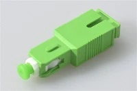
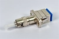
The adapter panel holds fiber optic adapters - the sockets that accept patch cords from downstream equipment. SC/APC adapters are the standard for FTTH and PON networks because their 8-degree angled polish pushes return loss below −60 dB, which matters for upstream transmission quality. LC adapters dominate in data center environments where port density is the priority. Mixing adapter types within a single FTB is technically possible with hybrid adapters, but it creates confusion during maintenance and should be avoided unless there is a clear technical reason. If you are unsure which connector ecosystem your site requires, this breakdown of the four common fiber optic connector types covers the tradeoffs.

Types of Fiber Terminal Box - and When Each One Makes Sense
FTB classification is not complicated, but the wrong choice for the environment is one of the most common procurement mistakes. Here is what separates the main types in practice, not just in theory.
Wall-mounted FTBs are the workhorse of FTTH and small-office deployments. They bolt to a wall or sit inside a weak-current distribution cabinet, support 2 to 24 fiber cores, and use a flip-open or removable cover. Installation takes minutes - two to four screws and a cable gland - which is why they get specified in high-volume residential rollouts where per-unit labor cost has to stay low. The tradeoff is limited splice tray space: if you need to integrate a PLC splitter or handle more than 24 cores, a wall-mount box gets crowded fast.
Rack-mounted FTBs go into standard 19-inch racks in data centers, central offices, and telecom shelters. They slide out for splice access, offer higher port density (24, 48, up to 96 fibers), and support both cross-connect and interconnect architectures. The additional cost per unit is justified in environments where cable management discipline and future scalability outweigh the price of the enclosure.
Outdoor FTBs are built for pole-mount or exterior wall-mount applications. Sealed gaskets, UV-resistant shells, corrosion-proof hardware, and operating temperature tolerance from roughly −40 °C to +75 °C. The IP rating is the single most important specification here - and one of the most frequently misjudged. An IP54-rated box works in a sheltered corridor. A pole beside a coastal highway needs IP68. Specifying by label ("outdoor rated") instead of by actual site conditions is how boxes fail in the field.
Desktop FTBs are lightweight, portable units for test environments, temporary splicing stations, or small sites where permanent mounting is impractical. They sacrifice environmental protection for convenience.

Quick Selection Reference
| Deployment Scenario | Recommended Type | Common Port Count | Adapter | Key Requirement |
|---|---|---|---|---|
| Indoor FTTH (single home) | Wall-mount | 4 / 8 | SC/APC | Compact size, splice tray for 1–2 cables |
| Apartment / MDU riser | Wall-mount or outdoor | 8 / 12 / 24 | SC/APC | Splitter compatibility, cable entry count |
| Data center / central office | Rack-mount | 24 / 48 / 96 | LC | Port density, slide-out tray access |
| Outdoor distribution point | Outdoor sealed box | 8 / 12 / 24 | SC/APC | IP65+ rating, UV and moisture resistance |
| Temporary / test site | Desktop | 4 / 8 / 12 | Varies | Portability, quick setup |
A useful rule of thumb: populate the box to about 60–70% of capacity on day one. The remaining headroom absorbs future growth without a full enclosure swap.
A few "do not" guidelines save more money than any selection chart. Do not use a wall-mount FTB if you already know a PLC splitter needs to fit inside - the tray space will be marginal at best. Do not assume IP65 covers every outdoor site; exposed pole mounts and coastal locations need IP68. And do not default to LC adapters just because they are smaller if the rest of the site is built around SC/APC - a connector mismatch costs more to fix than the density gain is worth.
Common Fiber Terminal Box Selection Mistakes
Most FTB problems are not caused by defective hardware. They are caused by specification errors made before the box is ever ordered. Four mistakes come up repeatedly.
Choosing the adapter type without checking existing patch cord inventory. In projects where the FTB is specified by one team and the patch cords are ordered by another, this goes wrong more often than it should. An SC/APC adapter panel is useless if the site already has a drawer full of SC/UPC jumpers. The angled-polish and flat-polish ferrules will physically mate, but the air gap at the interface creates a reflection spike that degrades PON upstream performance. Verify the connector ecosystem before locking in the adapter panel.
Selecting outdoor boxes by marketing label instead of actual IP rating. "Outdoor rated" is not an IP class. A box labeled "outdoor" might be IP54, which means it resists splashing water but not sustained rain or pressurized washing. If the installation site is exposed to weather, verify the specific IP number against the conditions the box will actually face - not the conditions the spec sheet assumes.
Underestimating spare port capacity. A 12-core box is slightly more expensive than an 8-core box. Replacing an 8-core box with a 12-core box two years later - including truck roll, re-splicing, and downtime - costs many times more than the price difference. Spec for growth.
Ignoring splitter form factor compatibility. If the deployment plan calls for integrating a PLC optical splitter inside the terminal box, the splice tray layout and enclosure depth must accommodate the splitter module - typically a mini-tube or ABS cassette form factor. Not every FTB is designed for this. Check the internal dimensions and tray configuration before assuming a splitter will fit.

Integrating PLC Splitters Inside Fiber Terminal Boxes
More FTTH operators now combine the splitting function and the termination function in the same enclosure. Instead of running fiber from a separate splitter cabinet to a downstream terminal box, the splitter sits directly on the FTB splice tray. The feeder cable fiber connects to the splitter input; each splitter output is fusion spliced to a pigtail that terminates on the adapter panel. Subscribers connect via drop cables plugged into those front-panel adapters.
This works because PLC splitters are wavelength-independent across the 1260–1650 nm operating band. A single integrated FTB can handle GPON downstream at 1490 nm, upstream at 1310 nm, and RF video overlay at 1550 nm simultaneously. No additional filtering hardware needed.
Fewer enclosures means fewer splice points, shorter fiber paths, and simpler documentation - less installation labor, less ongoing maintenance. The limitation is enclosure size: a wall-mount fiber optic terminal box with a 1×8 splitter leaves limited room for spare fiber storage, so the installation has to be clean. On projects where port count, adapter format, and splitter integration all need to be confirmed together, box layout matters more than the headline capacity on the datasheet. For detailed mechanics of how signals route through these enclosures, this technical walkthrough on how a fiber optic terminal box works covers the internal signal path.
Installation and Maintenance Practices That Actually Matter
Two installation steps cause the most field problems, and both are avoidable.
The first is contaminated splicing. A dirty fiber end introduces 0.3–0.5 dB of excess insertion loss per splice - enough to push a marginal PON link below the receiver sensitivity threshold. Clean every fiber end with lint-free wipes and IPA before cleaving. Inspect with a fiber microscope after cleaving. If there is any contamination visible, clean and re-cleave. The time spent on this step is trivial compared to the time spent troubleshooting a high-loss splice after the box is sealed.
The second is cable gland torque. Over-tightening crushes the cable sheath and stresses the fibers inside. Under-tightening allows moisture ingress over months. Follow the manufacturer's specified torque values. This is not a step where "hand tight plus a bit" is an acceptable substitute for a torque wrench.
For ongoing maintenance, fiber terminal boxes are passive and require minimal attention - but not zero. A practical schedule: visual inspection and connector end-face cleaning every 12–18 months for indoor installations, every 6 months for outdoor or harsh-environment sites. Check cable gland seals for cracking or compression set. If you maintain OTDR baseline records for each box, comparison traces will catch gradual splice degradation long before it causes a subscriber outage.
Frequently Asked Questions
Q: Do I Need SC/APC Or SC/UPC Adapters In An FTTH Fiber Terminal Box?
A: SC/APC in almost all cases. PON architectures are sensitive to back reflections, and SC/APC's angled ferrule delivers return loss below −60 dB compared to SC/UPC's −50 dB. The only common exception is point-to-point active Ethernet deployments where the reflection budget is more forgiving.
Q: What Is The Difference Between A Fiber Terminal Box And A Fiber Splice Closure?
A: A fiber terminal box terminates fibers and presents connectorized adapter ports for patch cord access. A splice closure protects mid-span splices between two cable segments but does not provide connector access. If you need to plug in patch cords or drop cables at the location, you need a terminal box. If you are just joining two cable runs in a buried or aerial location, a splice closure is the correct product.
Q: How Do I Choose Between 8-Core, 12-Core, And 24-Core FTBs?
A: Count the fibers you need to terminate today, then add 30–50% for future growth. A single-family FTTH drop usually requires a 4-core or 8-core box. An MDU riser serving 6–8 units needs 12 or 24 cores. If a PLC splitter will be installed inside the box, the splitter output count determines the minimum port requirement - a 1×8 splitter needs at least 8 output ports plus any pass-through fibers.
Q: Is IP65 Sufficient For All Outdoor Fiber Terminal Box Installations?
A: IP65 handles most sheltered outdoor locations - under eaves, inside street cabinets, or on building walls with some overhead protection. For fully exposed pole mounts, coastal installations, or areas with heavy dust or industrial particulate, IP68 with rubber-sealed gaskets is the safer choice. The cost difference is small relative to the cost of a field replacement.
Q: Can One Terminal Box Support Both Fiber Splicing And PLC Splitter Mounting?
A: Yes, many models are designed for this. The splice tray must have a dedicated area or mounting bracket for a mini-tube or ABS cassette splitter. Verify the internal dimensions before ordering - not all FTB enclosures have enough depth to accommodate a splitter module alongside standard splice holders and fiber storage loops.