Where the Loss Actually Happens in a Mated Pair
An adapter does not carry signal. It carries alignment.
Two ferrules enter from opposite sides, an internal sleeve holds them concentric within a couple of microns, and the spring load in each connector pushes the polished faces into physical contact. Everything the link experiences at that junction, meaning insertion loss, reflectance and repeatability across a re-patch, is decided by how well that mechanical job was done. A single-mode core is roughly nine microns across. The tolerance stack in a fiber optic adapter is not a rounding error against that number. It is the dominant term.
That is also why the field failure statistics look the way they do. Operators and test-equipment vendors have converged for years on the same finding: contaminated end faces, not broken fiber, are the leading cause of link failure, and most of the top fault categories are connector-related rather than cable-related. The specific numbers are worse than most buyers expect, and we come back to them near the end of this article, because they change how acceptance testing should be written.
Contamination migrates through adapters. A dirty ferrule mated into a clean port transfers particles to the port, and the port passes them to the next connector inserted. The adapter is the vector.
What follows is not a catalog of shapes. It is a walk through the fiber optic adapter types you will actually specify, organized around what goes wrong when each one is chosen carelessly.
Adapter, Coupler, Mating Sleeve: What to Write on the BOM
Three words circulate for the same object, and the ambiguity costs real time in procurement threads. "Coupler" is the older telecom usage and still common in North American distributor catalogs, though it collides awkwardly with optical splitters, which are also called couplers in photonics. "Mating sleeve" describes the function narrowly and tends to appear in test and instrumentation contexts. When deciding which of the three belongs on a fiber optic adapter purchase line, use "adapter". It is the term the interface standards use, and the one that will not be misread.
There is one distinction inside the family that does matter, and it is not a naming question. Bulkhead adapters mount through a panel, enclosure wall, or cassette face, and their flange and clip geometry has to match the cutout. Inline adapters simply join two cords in free air and have no mounting geometry at all. A purchase order that says "LC duplex adapter" without resolving that difference has a coin-flip chance of arriving unusable. Our own fiber optic adapter product range is organized around exactly these configuration fields for that reason.
Three Variables Decide Every Other Difference
Strip away the branding and the fiber optic adapter types on any distributor's filter page differ along three axes. Ferrule diameter sets which connector family fits. Sleeve material sets alignment precision and wear behavior. Polish geometry sets reflectance and determines what may never be mated to what.
| Variable | Options in practice | What it actually controls |
|---|---|---|
| Ferrule diameter | 1.25 mm (LC, MU), 2.5 mm (SC, FC, ST), rectangular MT ferrule (MPO/MTP) | Physical compatibility and achievable port density; a 1.25 mm plug will not seat in a 2.5 mm adapter |
| Alignment sleeve | Zirconia ceramic, phosphor bronze, hybrid split designs | Concentricity of the mated cores, repeatability across re-mating, and how loss drifts with cycle count |
| End-face polish | UPC (0°, domed), APC (8° angled) | Reflectance: roughly −50 to −55 dB for UPC against −60 to −65 dB for APC (ServeTheHome); also dictates which pairings are physically legal |
The sleeve row is where a common piece of shop-floor folklore deserves correction. The usual framing is that ceramic is for single-mode and bronze is for multimode, as if the two were parallel choices for parallel jobs. They are not symmetrical. A single-mode fiber optic adapter built around a ceramic sleeve works perfectly well on a multimode link, because excess precision costs nothing optically.
The substitution does not run the other way. A bronze-sleeved multimode fiber optic adapter used on single-mode fiber has an alignment tolerance that is loose relative to a nine-micron core, and the mismatch shows up directly as insertion loss.
So the honest position is that bronze is a cost decision, not an engineering one. In a mixed plant where technicians patch under time pressure and adapters get swapped between positions, standardizing on ceramic across the board removes an entire class of silent degradation for a difference in unit price that is small next to one truck roll.
The condition under which that recommendation stops holding is narrower than most people assume, and worth stating precisely: a genuinely closed multimode-only environment, with fiber optic adapter inventory controlled tightly enough that no single-mode cord can arrive at a bronze position during a move or an emergency repair. Sites that believe they meet that description usually fail the second half of it, not the first.
LC Adapters: What the 1.25 mm Ferrule Buys and What It Costs
The LC interface won the interior of the network on arithmetic. Its ferrule is half the diameter of SC's, which roughly doubles achievable port count in the same panel width. A 1U field populated with LC duplex adapters lands around 48 ports and 96 fibers, and since almost every SFP, SFP+ and QSFP breakout terminates in LC, the patch field usually just follows whatever the equipment presents. We covered the density arithmetic against array connectivity in more depth in our comparison of LC and MTP/MPO in high-density cabling.
The cost side is less discussed. A smaller ferrule means a smaller target for the alignment sleeve and a smaller margin for any particle that lands on it. The same speck of dust that would sit harmlessly on the cladding of a 2.5 mm multimode face can straddle the core on a single-mode LC. Density compounds handling error too. Forty-eight closely spaced duplex ports invite the technician to grip the adjacent cord while extracting one, and repeated side-loading is what wears the retention latches inside an LC fiber optic adapter long before the sleeve itself gives up.

The practical consequence is that an LC fiber optic adapter position rewards shuttered housings and a disciplined inspect-before-mate habit more than any other interface in the plant. Where that discipline does not exist, high density converts directly into a higher rate of intermittent faults.
Which raises the comparison people actually search for. In an LC vs SC adapter difference, the honest answer is not that one is better. They are optimized against opposite constraints: LC optimizes for ports per rack unit in a controlled room, SC for survivable handling in an uncontrolled one. Choose the fiber optic adapter format by which of those two constraints is binding on your site, and the rest of the specification follows.
SC Adapters: Why Access Networks Have Not Moved On
SC keeps getting described as legacy, and the description keeps being wrong at the access layer. Its 2.5 mm ferrule and simple push-pull latch tolerate field conditions such as cold hands, gloves, poor lighting and cabinets mounted at awkward heights far better than a small-form-factor latch does. The interface standard specifies a ferrule compression force in the range of about 7.8 to 11.8 newtons at nominal geometry, and that spring load is a large part of why the connection stays in physical contact after being handled roughly (IEC). For FTTH drops, PON distribution and outside-plant enclosures, an SC fiber optic adapter remains the default for reasons that have nothing to do with inertia.

The SC/APC variant carries a detail that changes how you specify unused ports. An unmated PC or UPC end face, whether it is dangling loose or sitting in an open fiber optic adapter position, reflects strongly. An open end face returns on the order of 14 dB, against the better-than-50 dB a single-mode span normally expects (Fluke Networks). In a point-to-point link that is a nuisance. In a split, broadcast-topology PON it is a genuine source of upstream disturbance, because that reflection is injected back into a tree shared by many subscribers. The same reasoning drives the polish and sleeve targets we set out in our FTTH passive component procurement guide.
That reframes the shuttered adapter. It is usually sold as dust protection and laser-safety hygiene, both of which are real, but the optical argument is the stronger one. Our position: on PON and FTTH distribution frames, shuttered SC/APC positions should be the specification default and open positions the exception requiring justification, not the other way around, which is how most tenders are still written.
One caveat before that becomes a blanket rule. A shuttered SC fiber optic adapter adds a moving part to a position that previously had none, and in dusty outside-plant cabinets the shutter mechanism itself becomes an inspection item. Specifying shutters without adding shutter operation to the incoming inspection list moves the failure mode rather than removing it.
Simplex, Duplex or Quad: The Field Most BOMs Guess At
Port configuration gets less discussion than keying or polish, and it appears on more purchase lines than either. The question of simplex versus duplex fiber optic adapter selection resolves cleanly once you separate two things that are easy to conflate: how many fibers the link needs, and how the panel is organized.
A duplex position carries a transmit and receive pair in one housing and one latch action, which is why it dominates anywhere a transceiver sits at the far end, including LAN patch fields, data center cross-connects and anything terminating in SFP. A simplex fiber optic adapter carries one fiber, and it is the correct choice in three situations that recur constantly: single-fiber bidirectional PON, where there is only one fiber to terminate; test and monitoring positions where a single strand is broken out deliberately; and distribution frames where fibers from different cables or different customers must be patched independently rather than as a bonded pair. Quad and multi-port housings exist mainly to raise density in a fixed panel cutout, and they trade away the ability to remove one position without disturbing its neighbours.
The failure mode here is quiet. A duplex fiber optic adapter ordered where the frame was laid out for simplex positions will physically mount and will accept cords, and the problem surfaces only when someone needs to re-patch one leg of a pair and finds the other leg mechanically bound to it.

MPO/MTP Adapters: Keying, Polarity and Gender
Everything above concerns a single pair of fibers. The moment an array connector enters the design, a variable appears that has no equivalent in the duplex world, and it is the one that turns correct-looking orders into dark links.
An MPO fiber optic adapter does not just hold two rectangular ferrules together. Its keyway orientation is a functional part of the polarity scheme.
Type A passes the array straight through: position 1 arrives at position 1. It achieves that by presenting one keyway up and one down, so a key-up connector mates with a key-down connector. Type B reverses the array: position 1 arrives at position 12. Its two keyways face the same direction, mating key-up to key-up. Ordering the wrong one does not produce a degraded link. It produces a dark one, because the transmit and receive mapping no longer lands where the transceiver expects it.
There is a constraint buried in that arrangement which almost never appears in adapter documentation. Type B is only available to flat-polished multimode connectors. Two APC ferrules cannot mate key-up to key-up, because their 8° faces would meet at a mutual angle rather than flush. Angled multi-fiber connectors can only be brought together key-up to key-down (Cabling Installation & Maintenance). Any design that assumes it can move an APC trunk onto a Type B polarity scheme by swapping adapters is going to stall at the panel.
Gender is the third variable and it is absolute. Every mated pair must be one pinned connector and one unpinned. Two pinned ferrules collide and can crush the guide pins or chip the ferrule face. Two unpinned ferrules have nothing establishing alignment and will never seat correctly. Because equipment-side MPO ports are pinned, anything plugged into active gear is unpinned, and trunk-to-trunk joins made through a panel therefore need the corresponding adapter gender to work out. We walked through the full polarity and gender decision chain in our MPO breakout cable guide.
Cleanliness scales badly here too. A particle larger than about nine microns can block a single-mode channel outright, and on a 24-fiber ferrule one contamination event sits across multiple channels at once. IEC 61300-3-35 exists precisely because a single visual judgment cannot handle this. It divides the end face into zones and sets separate defect allowances for each, so a particle that is acceptable on the ferrule body is not acceptable near the core. Our own MTP/MPO fiber optic adapter is specified at 0.2 dB maximum insertion loss, and that figure is only meaningful on an end face that has been inspected against those zones before mating.
Hybrid Adapters: What They Bridge and What They Must Never Bridge
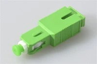
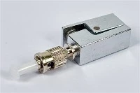
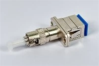
A hybrid fiber optic adapter joins two different connector families, such as SC to LC, FC to LC, SC to MU or ST to SC, by housing two different interface geometries around one alignment sleeve. It is a legitimate and useful part. It lets an installed base of SC-terminated distribution frames feed LC-terminated equipment without re-terminating anything, and it lets test instruments with FC bulkheads talk to an LC plant.

What a hybrid fiber optic adapter cannot do is bridge polish types, and this is the single most expensive misunderstanding in the category. An 8° APC face pressed against a 0° domed UPC face cannot achieve physical contact. The result is an air gap that sends reflectance sharply the wrong way, and mechanical contact concentrated on the edge of each face, which scratches or chips both. The damage is usually permanent. When it happens at an equipment port rather than on a cord, the repair is not a five-dollar patch lead. It is a transceiver or a line card.
Two things follow for anyone specifying. First, colour coding is a control, not a decoration: green housings for single-mode APC and blue for single-mode UPC exist to stop a tired technician at 2 a.m., and mixing housing colours for cosmetic reasons in a panel build actively removes a safety layer. Second, if a design genuinely has to cross polish types at a boundary, the correct answer is a purpose-built assembly with the transition handled inside a manufactured cord. Order a hybrid-polish part as such, like our FC/APC to LC/APC hybrid fiber optic adapter, where both sides are specified deliberately, rather than pushing two mismatched connectors into whatever housing happens to accept both bodies.
The Panel Side: Flange, Latch, Shutter, Cutout
When a shipment comes back, the reason is rarely optical. It is almost always that the part would not mount.
Flanged housings seat against the front face of the panel and are retained by clips behind it. Flangeless housings pass fully through and are retained differently, which is what cassette and some high-density systems require. Beyond that there are snap-in versus screw-mount retention, metal versus plastic bodies where EMI shielding or outdoor exposure is a factor, and shuttered versus open faces. None of these are visible in a photograph of the connector opening, and none of them are implied by the phrase "LC duplex adapter."
This is the single field we ask about most often before quoting, and the answer that causes the most trouble is the confident one. A buyer who says "standard flanged, same as before" is describing an incumbent part, not a dimension, and "same as before" has usually passed through two suppliers since it was last measured. When mechanical compatibility is critical, a bulkhead fiber optic adapter should be quoted against a panel cutout dimension, a drawing, or a physical sample, not against a model number from a datasheet nobody can still locate.
The interface standards have started to acknowledge how much this matters. The current edition of the SC interface standard, IEC 61754-4:2022, added dimensional requirements for the panel cutout specifically in the context of testing the strength of a mounted adapter, a recognition that mechanical fit and mechanical reliability are the same problem viewed from two sides. If you are matching a flanged fiber optic adapter into an existing frame, that is the measurement to send.
Loaded versus unloaded panels interact with this decision as well, and we treated that trade-off separately in our guide to choosing a patch panel or ODF.
How Long a Fiber Optic Adapter Actually Lasts
Datasheets routinely claim 500 or 1,000 mating cycles, and buyers routinely read that as a performance guarantee. It is not. Mating durability on a fiber optic adapter datasheet describes mechanical survival: after the stated number of cycles the housing still retains the connector, the latch still engages, the part has not fractured. Whether the mated pair still meets its original loss figure is a different test with a different acceptance criterion.
The wear pattern reported across the industry, and it is an industry observation rather than a figure from our own test bench, follows a familiar curve. The first few matings can read slightly high as the surfaces burnish in. Loss then sits flat for several hundred cycles. Somewhere past the mid-hundreds, sleeve wear and accumulated micro-damage start producing drift that shows up first as poor repeatability, meaning the same cord reads differently on consecutive insertions, before it shows up as an outright fault.
There is a further wrinkle that most suppliers have not caught up with. The relevant European performance standard was revised for 2026, and among its stated technical changes is a reduction in the required mating durability for cylindrical-ferrule connectors from 500 cycles to 200, alongside a newly specified 50-cycle requirement for rectangular-ferrule types (iTeh Standards). Any datasheet quoting "≥500 cycles, per IEC" is therefore citing a superseded basis, and a buyer who treats that number as a warranty is relying on something the standard no longer asks for.
Which is why a single replacement interval is the wrong output. Split the estate three ways. A trunk interconnect mated once during commissioning and never touched again will outlive the building. A patch position in an enterprise cross-connect, touched a few times a year during moves and changes, sits comfortably inside any of these ratings for its service life. A test-bench or turn-up position handled daily is a consumable. Only in that third category does replacing the fiber optic adapter every two to three years come out cheaper than the intermittent-fault investigations it prevents. Quoting that interval for the whole plant, as some maintenance specifications do, is just an inventory cost with no fault reduction behind it.
Why Insertion-Loss-Only Acceptance Misses Contamination
Most acceptance testing is a light source and a power meter, producing an insertion loss figure per link. That catches breaks, bad splices and gross misalignment. It has a specific and dangerous blind spot.
Industry end-face research has shown that oil contamination, the residue left by a fingertip touching a ferrule, degrades return loss substantially, on the order of 10 to 12 dB, while producing no significant change in insertion loss (EXFO). A contaminated connection can therefore pass an IL-only sign-off cleanly, sit in the plant looking healthy, and surface as a problem when a higher-rate service with a tighter reflectance budget is lit over the same path months later. Fiber optic adapter insertion loss, in other words, is the one number most acceptance procedures collect and the one number this particular fault does not move.
Here are the numbers promised earlier, and they land on the wrong budget line. Dell examined more than 500 optical modules that had been replaced in the field and returned as faulty, and found that 83% had nothing wrong with them. The same reference cites NTT Advanced Technology survey work in which 98% of installers and 80% of network owners identified connector end-face contamination as the greatest cause of network failure (Dell). Every one of those 500-plus returns was an RMA, a truck roll and a maintenance window spent replacing hardware that was working.
Two changes close the gap, and neither is expensive. Inspect before mating rather than after failure, since mating a contaminated face is what transfers the contamination and can cause permanent damage. And include reflectance in acceptance criteria on any single-mode span, particularly PON, where a reflection is a shared-medium problem rather than a private one. A fiber optic adapter position that passes on IL and fails on RL is exactly the case this catches.
Writing a Spec Line That Will Not Get You the Wrong Part
Most wrong shipments in this category trace back to a purchase line with four words in it. "LC duplex adapter, 200 pcs" is not a specification. It is the opening of a conversation that will happen either before shipping or after. Eight fields resolve essentially all of the ambiguity.
| Field | What to state | What happens if omitted |
|---|---|---|
| Connector interface | SC, LC, FC, ST, E2000, MU, MT-RJ, MPO/MTP; for hybrids, state both sides separately | Wrong ferrule size; part physically will not accept the cord |
| Fiber mode | Single-mode, multimode, OM3/OM4 where relevant | Wrong sleeve grade shipped against a single-mode link |
| Polish type | UPC, APC, or the specific hybrid combination required on each side | The costliest error class in the category; risk of permanent end-face damage |
| Port configuration | Simplex, duplex, quad, multi-port | Position count mismatch against the frame layout; bonded pairs that cannot be patched independently |
| Alignment sleeve | Ceramic or metal; specify explicitly rather than accepting default | Silent optical degradation that only surfaces during acceptance |
| Mounting and housing | Flanged or flangeless, snap-in or screw, metal or plastic, shuttered or open | Correct optically, unusable mechanically; the most common return reason |
| MPO detail | Fiber count, keyway type (A or B), gender, flange structure, housing colour | Dark link on turn-up, or crushed guide pins |
| Marking and packaging | Model number, label, barcode, housing and dust-cap colour, packing method | Warehouse and field identification errors at scale |
Two of those eight rows cannot be closed in writing, and knowing which two saves a sampling round. Mounting geometry and MPO keying are the fields where a text description and the physical part disagree most often: a cutout that everyone calls standard, a keyway described by the polarity method rather than the adapter type. When a fiber optic adapter order touches either row, we ask for a drawing or an incumbent sample before quoting rather than after, because the alternative is discovering the mismatch at the panel. The other six rows are settled by text alone.
The MPO row also behaves differently from the others in a second way. On every other line an omission produces a part that is wrong in a visible way, whereas an unstated keyway produces a part that looks correct, installs correctly, and fails only when traffic is applied.
When a supplier reads a line like that back to you before quoting, that is the process working. The pattern we see is narrower than "buyers forget things". Interface, mode and port count are almost always present, and polish type on the second side of a hybrid is almost always absent, because the person writing the line is thinking about the connector they are converting from and not the one they are converting to. A quotation for fiber optic adapter types that comes back priced instantly against a four-word description has substituted an assumption for a specification, and the assumption surfaces later.
FAQ
What is the difference between a Type A and a Type B MPO fiber optic adapter?
A Type A adapter is keyed up-to-down and passes the array straight through. A Type B adapter is keyed up-to-up and reverses it, and Type B is only usable with flat-polished multimode connectors.
Can a hybrid fiber optic adapter connect an APC connector to a UPC one?
No. Hybrid adapters bridge connector families, never polish types, and forcing an angled face against a domed one usually damages both permanently.
Why do fiber optic adapters use ceramic sleeves for single-mode and bronze for multimode?
Because a nine-micron single-mode core needs the tighter alignment tolerance zirconia holds. The substitution only runs one way: a single-mode adapter is safe on a multimode link, while a bronze-sleeved part on single-mode fiber adds measurable loss.
How many mating cycles does a fiber optic adapter really survive?
Ratings of 500 to 1,000 cycles describe mechanical survival, not sustained optical performance, and the current European performance standard has reduced the required figure for cylindrical-ferrule types to 200.
Does an unused fiber optic adapter port matter optically?
Yes, on single-mode. An unmated UPC face returns roughly 14 dB, which is enough to disturb upstream traffic on a shared PON tree, and that is the real argument for shuttered positions.
Sourcing Fiber Optic Adapters for a Project or a Product Line
If a specification arrives without a keyway type, most suppliers will not stop the order to ask. They will ship the most common configuration, which is Type A, and the mismatch will be discovered by whoever is standing at the panel on turn-up night.
That is the part of the process we handle differently. Configuration gets confirmed against a drawing, an existing datasheet or a physical sample before anything is sampled or produced, because the fields most likely to be missing from an inquiry are precisely the ones that cannot be inferred from a part description: polish type on each side of a hybrid, keyway and gender on an MPO, cutout geometry on a bulkhead housing. Production then runs against that approved reference, and verification covers both halves of the problem. On the mechanical side that means overall dimensions, panel fit, insertion and withdrawal force, connector retention, shutter operation and key orientation. On the optical side it means mated-pair insertion loss, connection repeatability, mating durability and environmental reliability. Ten-plus years of building these parts in Shenzhen has mostly taught us that the mechanical column is where the field failures actually originate.
If you are matching adapters into an existing frame, developing a private-label range, or resolving a BOM line that has already come back wrong once, send the drawing, the datasheet or the incumbent part. Our team will confirm the configuration before sampling, so you can request fiber optic adapter samples or a configuration review here.
A fiber optic adapter is a precision mechanical part sold at a commodity price, and the gap between those two facts is where projects lose time. Closing it costs one drawing and one email.