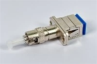
We designed this guide to help network engineers make key decisions about FC interfaces. We analyze the physical differences between APC and UPC endfaces. We also address key width matching traps and provide clear B2B buying specifications. The optical communication industry continuously pushes for higher port densities. Because of this trend, many facility managers overlook the mechanical benefits of older connector types. We provide this analysis so infrastructure specialists can specify, buy, and deploy these threaded connectors in tough working environments.
The Role of FC Connectors in Modern Optical Infrastructure
High-density data centers favor smaller interfaces. Even so, the fc fiber connector remains irreplaceable in high-vibration settings and older telecom backbones. We evaluate connector lifespan using standard mating cycles. The 500 FC connector mating cycles provide an adequate baseline for static setups. This matches the 500 LC connector mating cycles defined in the 61754-20 IEC specification for LC connector used in dense switching areas. The 1000 SC connector mating cycles outlined in the 61754-4 IEC specification for SC connector offer higher durability for frequent patching. However, the 61754-13 IEC specification for FC connector defines a threaded coupling mechanism. This design provides superior mechanical isolation under continuous industrial vibration.
Engineers choose FC interfaces when connection stability matters more than port density. This is especially true in military, aerospace, and heavy industrial fiber setups. Modern networking gear rarely includes FC ports by default. Therefore, buying teams must source special hybrid patch cords for system integration. We must evaluate the mechanical environment of the site before replacing older FC distribution frames with modern high-density LC cassettes. The threaded design stops the tiny shifts that cause sudden signal drops in push-pull connectors during heavy machinery work or earthquakes. Screwing the connector into place takes more time. We recognize that this extra installation time is a necessary trade-off for mechanical stability.
Core Mechanics: Threaded Coupling and Ferrule Geometry
The threaded coupling mechanism prevents accidental disconnects in industrial or high-vibration settings. It works by locking the connector body directly to the mating socket. We rely on the EIA/TIA-604-4 standard for FC fiber optic connector intermateability to ensure consistent dimensions across global makers. The optical fiber rests inside a 2.5 mm FC connector ferrule size. Makers build this ferrule from high-precision zirconia ceramic or stainless steel.
This sturdy setup uses a spring-loaded floating ferrule design. This spring isolates the fiber endface from outside cable pull and mechanical stress. When a technician tightens the threaded collar, the internal spring compresses. This action maintains constant physical contact pressure between the two mating ceramic ferrules. Because of this mechanical isolation, pulling the outer cable jacket does not harm the optical signal or drop the connection.
We require engineers to hand-tighten these connectors to a specific torque level. Overtightening can ruin the housing or strip the fine threads. We frequently observe field failures where technicians use pliers to tighten the coupling nut. This practice permanently bends the internal spring. The precision of the zirconia ceramic ferrule ensures that the nine-micron single-mode fiber core aligns with the receiving port to cut signal loss. Technicians should use dust caps whenever the connector is unplugged. The bare 2.5 mm ceramic tip catches dirt easily.
Comparing FC APC and FC UPC optical performance
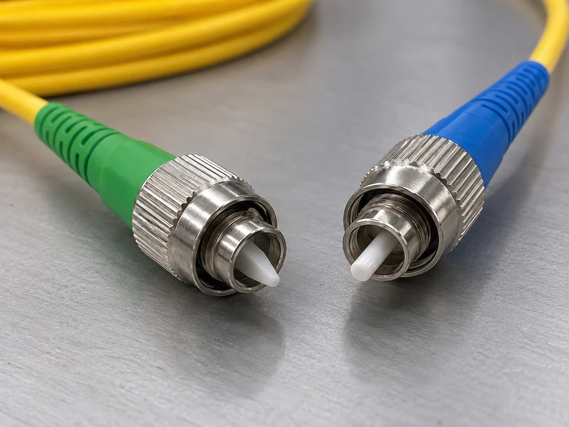
fc apc vs fc upc demonstrates that polish types set the return loss of the link, while insertion loss stays almost identical. The 8° typical industry standard angle for APC polish forces reflected light to leak into the fiber cladding. This keeps the light from bouncing back toward the laser source. We observe a ~ -50 dB typical return loss for UPC fiber connector setups. This level easily meets the needs of most standard digital data systems. The angled shape achieves a ~ -60 dB typical return loss for APC fiber connector setups. This makes it mandatory for sensitive analog video signals and long-haul links.
Modern manufacturing has balanced forward attenuation. This yields a ≤ 0.3 dB typical insertion loss for APC and UPC connectors across reputable suppliers. Many community users report an 87% APC polish reflection reduction over UPC. However, official maker documentation does not confirm this exact ratio. Some field technicians report a higher chance of cracking regarding APC connector durability with frequent disconnects. This issue requires careful handling during routine maintenance and patching.
We must clarify technical terms because engineers often confuse positive return loss values with negative reflectance values on spec sheets. Return loss measures the ratio of input power to reflected power in positive decibels. Here, a higher number shows better optical performance. Reflectance measures the ratio of reflected power to input power in negative decibels. In this case, a lower negative number indicates a better connection.
| Polish Type | Ferrule Geometry | Typical Return Loss | Typical Insertion Loss |
|---|---|---|---|
| UPC | Flat with slight dome | ~ -50 dB | ≤ 0.3 dB |
| APC | 8° angled surface | ~ -60 dB | ≤ 0.3 dB |
The Key Width Trap: FC/APC Narrow-Key vs Wide-Key Interfaces
Buying and field teams often run into severe signal loss caused by mismatched alignment keys on FC/APC angled connectors. The alignment key keeps the ferrule from turning during coupling. This step is critical for aligning the two angled glass endfaces properly. The ≤ 2.14 mm FC/PC plug key width sets the baseline size for flat-polished connectors that do not need strict rotational alignment.
For angled connectors, the 2.09–2.14 mm FC/APC type N (wide key) plug key width matches standard PC sizes and fits standard sockets. Conversely, the 1.97–2.02 mm FC/APC type R (narrow key) plug key width needs a matching narrow socket to hold the correct angle. Forcing a narrow-key plug into a wide-key adapter allows the connector to twist. This twists the 8-degree angled cores out of alignment and causes heavy signal loss across the link.
Engineers must check the exact key width of their equipment ports before ordering patch cords to prevent major setup failures. Teams should standardize on the Type N wide key format for new setups. It provides broader compatibility with standard FC/PC bulkheads. We often identify key width mismatches during testing when optical time-domain reflectometer traces show unexpected insertion loss spikes at patch panels.
- FC/PC plug: ≤ 2.14 mm key width
- FC/APC type N (wide key) plug: 2.09–2.14 mm key width
- FC/APC type R (narrow key) plug: 1.97–2.02 mm key width
Application-Based Selection Matrix
Port specs and reflection sensitivity determine whether an engineer must deploy APC or UPC connectors for a project. Cable television networks and single-mode lasers require APC interfaces. Analog signals degrade fast when reflected light destabilizes the source laser. Older telecom systems and standard data center gear usually use UPC interfaces. Digital systems can handle minor reflections without dropping data packets.
We evaluate the link budget and site conditions to choose the right polish for special industrial uses and test gear. Teams should standardize on one polish type per site whenever possible. This practice lowers the risk of technicians mating the wrong connectors. We deploy APC connectors in passive optical networks because high-power lasers are vulnerable to back-reflection damage. We specify UPC connectors for multimode fiber systems because the wider core limits the impact of reflections on short-reach data runs. We ensure every part in the optical path matches the specified polish type. This includes bulkheads, patch cords, and active transceiver ports.
| Application / Equipment Type | Reflection Sensitivity | Recommended FC Polish |
|---|---|---|
| Cable Television (CATV) | High | FC/APC |
| Single-Mode Lasers | High | FC/APC |
| Optical Measurement Equipment | High | FC/APC |
| Legacy Telecom Systems | Low to Moderate | FC/UPC |
| Standard Data Center Equipment | Low | FC/UPC |
The Catastrophic Mistake: Mating FC/APC Directly with FC/UPC
Plugging an angled APC connector directly into a flat UPC connector causes immediate optical failure. It also permanently damages the glass cores. The shape mismatch keeps the fiber cores from touching. This creates an air gap that destroys the return loss performance of the whole link. We expect a -20 dB typical reflectance for flat with air gap connection. This will quickly destabilize sensitive transmitters and trigger system alarms.
The threaded coupling applies high pressure to the mismatched ceramic ferrules. This force often crushes the fragile glass cores at the uneven contact point. We resolve equipment mismatch issues by specifying custom hybrid patch cords from specialized manufacturers like EVOLUX Fiber for cross-platform integration. A properly configured hybrid cord features an FC/APC connector on one end and an SC/UPC connector on the other. This ensures perfect physical alignment.
We train technicians to check the strain relief boot colors. APC connectors use green boots, while UPC connectors use blue boots. Checking these colors prevents accidental cross-mating. We require replacing both connectors if a technician mates an APC plug with a UPC socket. Microscopic cracks from the impact will degrade future performance. We document the optical time-domain reflectometer signature of a mismatched connection. It shows up as a huge reflection spike followed by a sharp drop in power.
- Standard compliance requires adhering to EIA/TIA-604-4 and IEC 61754-13 intermateability specifications to guarantee mechanical alignment across all mated assemblies.
- An 8° angle on the polished endface directs light reflections into the cladding, yielding a target return loss of approximately -60 dB for angle-polished links.
- A standard physical contact polish delivers approximately -40 dB return loss, while ultra-polished interfaces achieve approximately -50 dB to protect source lasers.
- Proper geometric alignment ensures an insertion loss threshold of ≤ 0.3 dB across properly terminated physical contact and angled interfaces.
- FC and LC interfaces are rated for 500 mating cycles, whereas SC hardware supports up to 1000 mating cycles before mechanical wear degrades signal transmission.
- A type N wide-key plug measuring 2.09–2.14 mm will fail to seat inside a 2.03–2.08 mm type R narrow-key receptacle, preventing accidental engagement.
- A type R narrow-key plug measuring 1.97–2.02 mm inserted into a standard 2.15–2.20 mm keyway causes rotational misalignment that degrades polarization extinction ratios.
Inspection, Testing, and Factory Acceptance Criteria
We set strict factory acceptance rules because average performance data does not guarantee the limits of individual cables. Engineers must inspect every ferrule endface with a digital microscope before mating. Do this regardless of dust caps or supplier reputation. We review insertion loss and return loss data in maker test reports to ensure links meet our budgets. EVOLUX Fiber provides detailed factory records. These files separate batch averages from guaranteed worst-case insertion loss limits for every shipped unit.
We reject orders if the paperwork confuses positive return loss with negative reflectance. That mix-up signals poor quality control and bad testing methods. The fc fiber connector should have its insertion loss tolerance standards set at a maximum of 0.3 dB per mated pair for critical infrastructure deployments. We perform the FC connector return loss measurement procedure using an optical continuous wave reflectometer to verify that the installed links meet the specified parameters.
We require suppliers to use standard reference cords during factory testing. This ensures measured insertion loss reflects true connector performance. We throw out any patch cords that fail the 60 dB return loss target for APC polish. Subpar parts hurt overall system stability.
| Step | Verification Focus | Acceptance Threshold |
|---|---|---|
| Visual Inspection | Ferrule endface cleanliness and scratches | Zero defects across the core and cladding zones |
| Insertion Loss Testing | Forward optical power attenuation | Maximum 0.3 dB per mated pair |
| Return Loss Testing | Back-reflected optical power | Minimum 50 dB for UPC, 60 dB for APC |
| Key Width Verification | Physical plug dimensions | Exact match to the specified Type N or Type R standard |
- Conformance with EIA/TIA-604-4 and IEC 61754-13 ensures full mechanical intermateability across all single-mode hardware.
- Ceramic or stainless steel ferrules must maintain an outer diameter of 2.5 mm to guarantee precise axial core alignment within mating sleeves.
- Angled end-faces require an 8° polish angle to direct optical back-reflection into the cladding rather than the core.
- Physical contact connectors must achieve a return loss of approximately -40 dB to prevent destabilizing reflections in standard laser transmitters.
- An unexpected reflectance reading near -20 dB indicates an improper flat connection with an internal air gap.
- Hardware must maintain stable optical continuity across a minimum rating of 500 mating cycles to prevent premature link degradation.
- Narrow keyway installations require plug keys sized between 1.97 mm and 2.02 mm to prevent rotational misalignment on polarization-maintaining lines.
- Wide keyway hardware requires plug keys sized between 2.09 mm and 2.14 mm to prevent mechanical jamming during insertion.
B2B Procurement: RFQ Specification Template
A clear Request for Quotation stops project delays caused by missing key width or polish specs on the purchase order. We require buying teams to define every physical and optical spec. This removes guesswork during assembly. We observe a negligible cost difference between FC APC and UPC connectors. Therefore, engineers should pick the polish type based solely on technical needs.
Specify the exact cable outer diameter in the order. Industrial settings often need 3.0 mm armored jackets instead of standard 2.0 mm patch cords. We tell buyers to get detailed mechanical drawings from the vendor before approving production of custom hybrid cables. We verify that the supplier holds ISO 9001 certification and uses a cleanroom to assemble and polish ceramic ferrules. We require serial numbers on every patch cord to track parts and simplify field troubleshooting. We reject bids from suppliers that hide factory acceptance rules or only list typical averages in sales brochures.
- Connector Type: FC at both ends, or specific hybrid configurations matching the equipment ports
- Polish Type: APC or UPC, explicitly defined for each end of the cable assembly
- Key Width: Type N (wide) or Type R (narrow) explicitly stated for all APC connectors
- Fiber Type: Single-mode (OS2) or multimode (OM3/OM4) matching the network infrastructure
- Cable Diameter: 2.0 mm, 3.0 mm, or 900 µm buffered fiber depending on the routing environment
- Length: Exact meter measurement with acceptable tolerance limits defined in the contract
- Jacket Material: PVC, LSZH, or OFNP plenum rated
- Optical Performance: Maximum acceptable insertion loss and minimum acceptable return loss per connector
- Testing Documentation: Requirement for individual IL/RL test reports attached to every cable bag
- Labeling and Packaging: Custom serial numbers and protective dust caps applied before shipping
Frequently Asked Questions
The fc fiber connector presents common deployment and compatibility questions that we address to assist field technicians with troubleshooting.