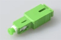
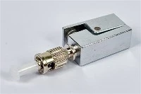
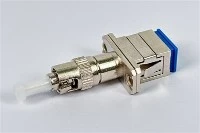
An MT-RJ fiber optic adapter should be selected against the interfaces it will join and the panel it must fit. Confirm the mating configuration, keying, mounting drawing, fiber specification and optical acceptance requirements before approving a substitute. A matching product name alone is insufficient evidence of compatibility.
This guide helps buyers specify replacement or project components for an EVOLUX enquiry. Manufacturer references explain interface principles and illustrate documentation to request; they do not establish interchangeability with EVOLUX products.
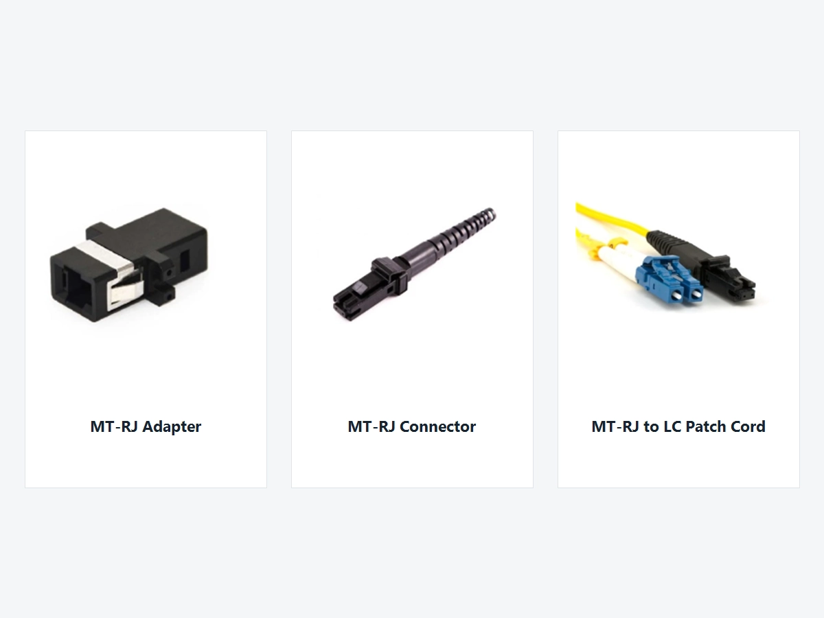
Identify the Adapter You Actually Need
Mating Adapter, Panel Assembly or Loopback?
Start the purchase description with the function of the item. The word "adapter" can refer to different purchasing objects, so ask whether the quotation covers an individual mating component, a loaded panel or a diagnostic accessory.
| Purchasing object | What the order should identify | Decision before requesting a quote |
|---|---|---|
| Passive MT-RJ mating adapter | The component used to couple compatible MT-RJ terminations | Whether only the adapter is required or associated cable components are included |
| MT-RJ panel assembly | The plate or module and its fitted components | The enclosure, loading arrangement and supplied hardware |
| MT-RJ loopback | A diagnostic item that returns an optical transmit path to a receive path | Whether the purpose is equipment testing rather than extending a link |
OCC publishes MT-RJ adapter plates with individual part numbers and drawing links. This is a useful example of why a panel assembly needs its own identification rather than only the connector-family name. Networx describes its MT-RJ loopbacks as equipment-testing accessories that return transmitted signals to receiving ports. These are commercial manufacturers' descriptions of their own products. (OCC; Networx)
If the interface family itself is still uncertain, use the fiber optic adapter interface guide before specifying an MT-RJ replacement. Once the family is established, the remaining questions concern the exact connection and mounting arrangement.
Check Both Mating Interfaces
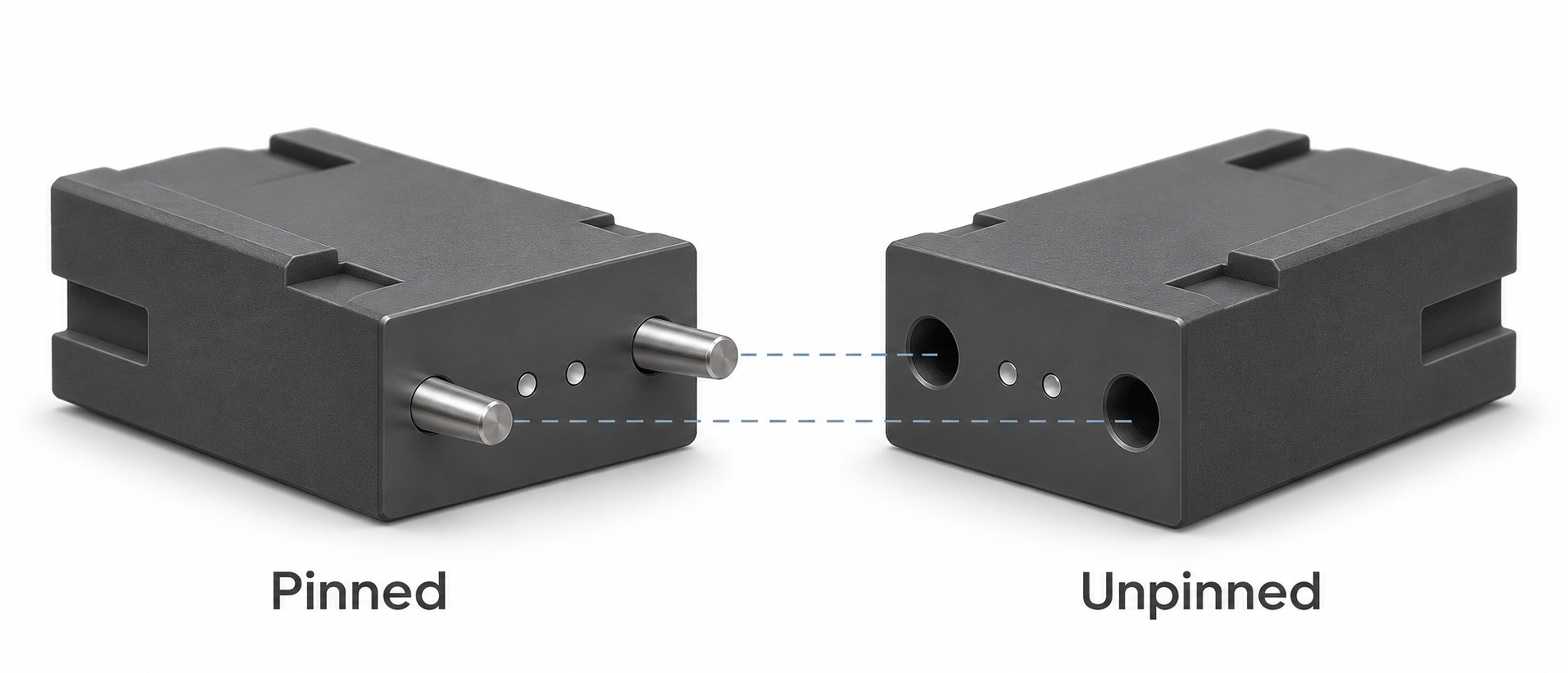
Pinned and Unpinned Ends
MT-RJ carries two fibers in one polymer ferrule. Corning's AEN058 assigns coarse alignment and retention to the adapter, with precision alignment provided by connector guide pins and matching holes. The intended mating pair has one pinned and one unpinned interface. (Corning application note AEN058)
| Interface A | Interface B | Procurement decision |
|---|---|---|
| Pinned | Unpinned | Correct pin arrangement; verify the remaining specifications |
| Pinned | Pinned | Reject this pairing |
| Unpinned | Unpinned | Reject as a properly aligned connection, even if the housings latch |
Do not remove pins to make a mismatched part fit. Corning warns against this modification. Its note contains differing revision and publication labels, so it is used here for the stated interface principle, not as a current equipment approval.
Equipment Port and Cable-End Identification
For each connection, identify the equipment port or opposite cable termination from its own documentation. Avoid inferring pin configuration from a seller's "male/female adapter" label. Request an annotated interface view if the description is ambiguous.
Create one connection record per mating location. Give each side an identifier, its manufacturer part number and the relevant drawing or photograph. State the viewing direction-such as looking into the equipment port-so the supplier can relate the evidence to the actual installation. For a populated patch panel, include the rear termination in that record.
Verify Keying and Panel Fit
Drawing, Cutout and Retention Details
A mechanically suitable replacement must match the installed mounting arrangement as well as the connector interface. Corning's adapter family specification, revised March 26, 2019, includes keyed, full-flange MT-RJ options, while OCC lists separate adapter-plate drawings. These product examples show why the selected part number and drawing matter; they do not prove cross-brand interchangeability. (Corning catalog; OCC)
Use the following as a purchasing review, rather than a universal dimensional specification:
| Drawing item | What to verify | Evidence to retain |
|---|---|---|
| Keying | Exact key feature and permitted connector orientation | Interface drawing and the matching connector identification |
| Panel cutout | Opening shape, dimensions and tolerances | Existing panel drawing and proposed adapter drawing |
| Retention | Flange, fasteners or snap-in features, as applicable | Installation detail and supplied-hardware list |
| Panel thickness | Suitability of the retention feature for the actual panel | Drawing or written supplier confirmation |
| Installed clearance | Space for connector insertion, latch access and cable routing | Assembly view with surrounding components |
| Revision | Consistency of the quoted and approved configuration | Controlled part number and drawing revision |
Do not assume that keyed and non-keyed products are interchangeable because their outer housings look similar. Confirm the exact key arrangement against the mating connector documentation.
For a replacement in a fixed panel, compare the proposed part directly with the existing cutout and rear clearance. If the panel drawing is unavailable, record measurements and photographs for supplier review; treat them as inputs to confirmation rather than a substitute for an approved fit assessment.
For a new panel design, select the adapter configuration before releasing the cutout. If an alternative is proposed later, review its mounting drawing before accepting it as an equivalent. A general "MT-RJ compatible" statement does not resolve enclosure fit.
Confirm Fiber Type and the Two-Fiber Path
A passive MT-RJ adapter does not convert single-mode fiber into multimode fiber, or vice versa. Mechanical fit does not establish optical-link compatibility: the cable fibers and equipment requirements must also match the intended configuration.
For the RFQ, record the adapter part number and stated application range separately from the cable fiber specifications, equipment requirements, operating wavelength and required mapping of both fibers. Include the viewing direction and endpoint labels. Do not infer these requirements from housing color or the MT-RJ name.
For a like-for-like replacement, verify that the proposed part preserves the approved configuration. If the equipment or cable configuration changes, use the equipment-port and fiber compatibility checks to review the complete path before approving the adapter.
Compare Supplier Evidence on the Same Basis
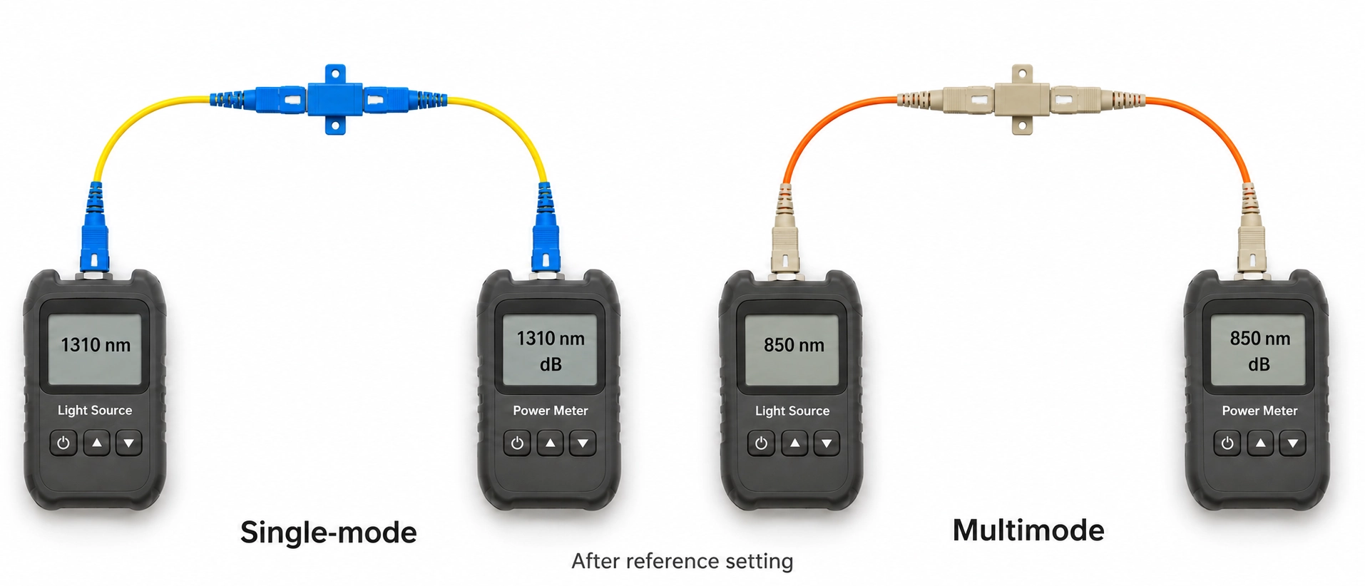
What an Optical Test Report Must Identify
A quoted insertion-loss value is useful only when its measurement boundary is clear. Ask whether it describes a defined mated connection, a cable assembly or an installed link. FOA explains that reference arrangements affect the connections included in an insertion-loss measurement; consequently, results from unspecified reference setups are not directly comparable. (FOA)
At quotation stage, request the test-path description, reference arrangement, wavelength, identified test cords, results for both fiber paths and the applicable acceptance limit. These are procurement evidence fields, not a standard test procedure; agree the actual method with the responsible test specialist.
Keep dimensional conformity separate from optical performance. IEC describes IEC 61754-18:2001 as defining interface dimensions for the MT-RJ connector family. This reference uses the public catalog scope, not the paid standard's detailed clauses. That scope alone does not establish a supplier's batch performance or certify the proposed product. (IEC)
Link the supplier's evidence to the quoted part number and configuration. A family-wide marketing table does not establish which performance claims apply to the proposed MT-RJ part.
Use the MT-RJ inspection and acceptance checklist for the subsequent inspection, optical testing and release records. This guide defines the purchasing specification and evidence to request before those checks.
Prepare an MT-RJ Adapter RFQ
An RFQ should let the supplier identify unresolved requirements before quoting an alternative. The table below is a reusable purchasing framework; it is not a standardized MT-RJ test form or an EVOLUX product specification. Write "supplier to confirm" wherever a field remains unresolved.
| RFQ field | Information to supply or request |
|---|---|
| Purchasing object | Individual mating adapter, loaded panel assembly or loopback; state included components |
| Existing item | Manufacturer, part number, revision and replacement reason, where available |
| Mating interfaces | Identification of both sides at each connection, including pinned/unpinned configuration |
| Keying | Required key arrangement, supported by a drawing or annotated view |
| Mounting | Panel cutout, thickness, retention method, hardware and installation clearance |
| Equipment identification | Equipment manufacturer and model; transceiver/module model, where applicable; equipment port part number or interface drawing |
| Optical configuration | Fiber specification on each side, equipment requirements and operating wavelength |
| Fiber mapping | Required path for both fibers, including viewing direction and endpoint labels |
| Evidence requested | Proposed-part drawing, configuration confirmation and applicable test documentation |
| Acceptance basis | Agreed sample checks, optical limits and test method for the defined configuration |
| Supply requirements | Sample and production quantities, packaging needs and requested delivery schedule |
| Substitution control | Written approval required for changes to part, keying, mounting or test configuration |
If all interface and mounting details are documented, request confirmation against the named configuration and agree the sample approval criteria. If an interface is unidentified, resolve it before accepting a substitute; state the missing item explicitly rather than allowing it to become an unstated assumption in the quotation.
To request an MT-RJ compatibility review, send EVOLUX the completed RFQ, equipment and module identification, both interface views, the mounting drawing and required quantities. Use the enquiry form or the email listed on the contact page; send drawings and photographs by email if the form does not support attachments. Request written confirmation of the proposed part number, any unresolved requirements and the documents needed for sample approval.