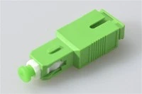
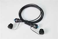
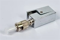
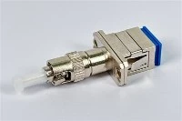
An MT-RJ fiber optic connector should be accepted against an identified specification, with evidence of compatible mating, clean end faces and the required optical performance. For a terminated cable assembly, the record must also cover both fibers and their specified end-to-end mapping. A housing that fits and a single passing loss result do not establish that the complete assembly meets its requirements.
This guide helps engineers and buyers define the checks and evidence needed for acceptance. It is a reference framework, not a product-specific test procedure. It does not establish universal loss limits, sampling rates or mechanical qualification requirements. Apply the approved requirements for the component, assembly or installed link being evaluated.
Define What You Are Accepting
Connector, Adapter or Cable Assembly
Start by identifying the item on the purchase order and the boundary of the test. Connector components, passive mating adapters and terminated cables require different evidence. An installed link has another boundary again.
| Acceptance object | What to establish | Appropriate evidence to request |
|---|---|---|
| Unassembled connector components | Correct parts, dimensions and configuration | Approved drawing, part identification and applicable component inspection records |
| Passive mating adapter | Correct interface, mounting and retention; performance of the specified mating arrangement where required | Adapter specification and results identifying the reference connectors, optical path and method |
| Terminated cable assembly | End configuration, both fiber paths, end-face condition and specified optical performance | Assembly drawing, mapping record, inspection evidence and per-fiber test results |
| Installed link | Actual endpoints and the complete defined test path | Link identification, reference configuration and results against the approved link requirements |
This is a proposed evidence framework, not a standard's acceptance table. A passive adapter evaluated between reference connectors is part of a defined optical path. Report that configuration rather than presenting the complete measurement as an independent optical result for the bare adapter.
Before inspection begins, identify the applicable part number, drawing revision, acceptance specification and authorized release process.
Confirm Interface and Mating Compatibility
Pins, Fiber Type and Two-Fiber Mapping
Record the pinned or unpinned configuration of each mating interface, including the equipment port and test reference cords.
Corning's MT-RJ application note, AEN058, explains that precision alignment requires guide pins in exactly one connector of a mating pair. Two unpinned connectors lack the required precision alignment; two pinned connectors cannot mate correctly. It also warns against removing pins to change the configuration. Confirm the actual port documentation before connecting anything.
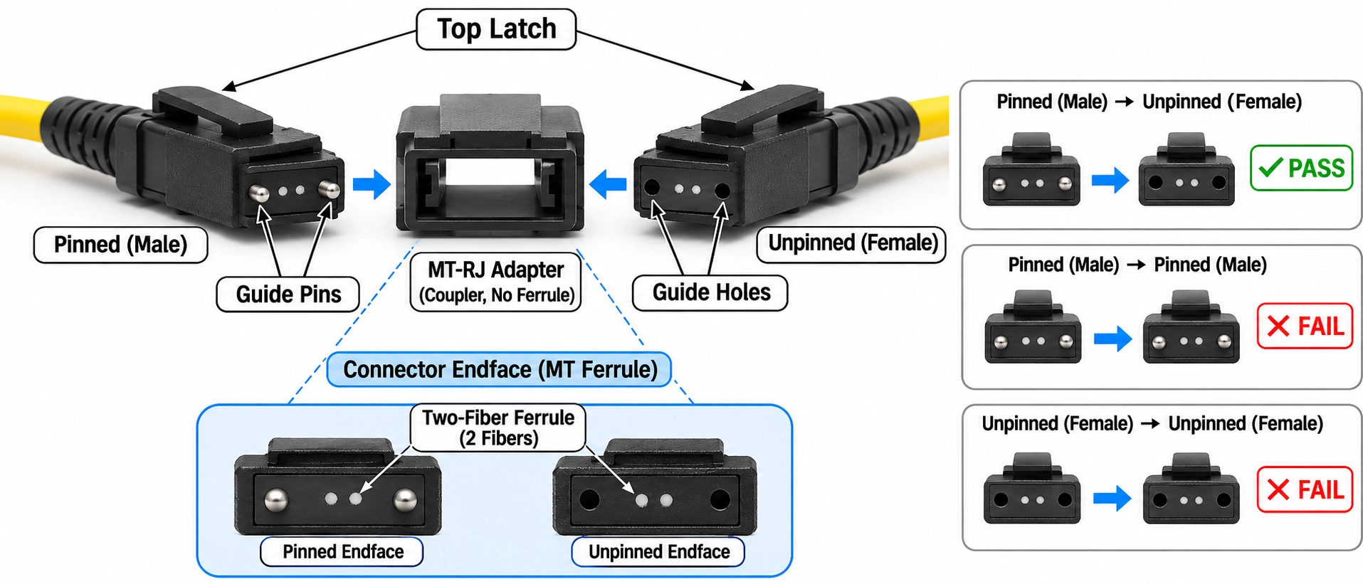
The interface drawing should identify each connector end, its mating partner, pin configuration, latch orientation and viewing direction. A description such as "front view" must make clear whether the reader is looking into the mating face or toward the cable.
Do not infer fiber mode from the MT-RJ name alone. US Conec's public AEN-1601, Rev. 2.0 metadata lists two fibers and both multimode and single-mode fiber types. That establishes the scope of the listed procedure, not compatibility between every MT-RJ product and every port. Confirm the ordered fiber type and equipment requirements.
For broader interface-selection background, consult the fiber optic adapter interface selection guide. The approved MT-RJ drawing remains the acceptance reference.
Use the following blank mapping template with the order drawing. It does not prescribe straight-through or crossed wiring.
| Path record | End 1 physical position, as defined in the drawing | Required End 2 position | Verified End 2 position | Associated test record |
|---|---|---|---|---|
| Path 1 | - | - | - | - |
| Path 2 | - | - | - | - |
Record the drawing number, revision and viewing convention with the completed table. "Path 1" and "Path 2" are record identifiers, not standardized connector-position names. Do not substitute MPO polarity classifications for an MT-RJ mapping drawing.
Prepare Compatible Inspection and Cleaning Tools
Confirm the inspection system as a combination: instrument, probe tip, any required barrel assembly, software settings and the interface being inspected. Physical access alone does not demonstrate adequate inspection coverage.
VIAVI's March 2026 inspection-tip selection guide lists the FBPT-MTRJ-1 MTRJ bulkhead tip with an FBPP-BAP1 or FBPP-BAP2 barrel assembly. This is a specific accessory listing, not a declaration that the combination covers every MT-RJ plug, receptacle or equipment port. Verify the supported device and access arrangement with the manufacturer.
Select cleaning tools for the actual pin configuration. Corning's SRP-006-056, Issue 10, May 2014, distinguishes cleaning areas for MT-RJ with pins and pin-less MT-RJ and includes microscope inspection after cleaning. Follow the instructions for the selected tool rather than copying the motion used on an unrelated connector.
Before inspection or cleaning, turn off and isolate optical sources according to the equipment procedure. Never look into a fiber or connect it to a fiberscope while system lasers are on. A disconnected connector can still emit invisible radiation from a source at the other end. Cisco's inspection and cleaning guidance, updated in November 2016, includes these precautions.
For the inspection record, identify the instrument, tip, accessories, inspection procedure and applicable calibration or verification status.
Inspect Both Fibers and the Ferrule Contact Area
Inspect each fiber end face and document the required contact-area coverage. A clear image of one fiber does not establish the condition of the other.
The public description of IEC 61300-3-35:2022 distinguishes fiber-zone examination from contamination inspection of the contact area. For rectangular ferrules, it identifies the whole ferrule surface as the contamination-inspection area. It also states that visual inspection supplements rather than replaces attenuation, return-loss or end-face-parameter measurements. Use the applicable standard and approved procedure for detailed classification criteria.
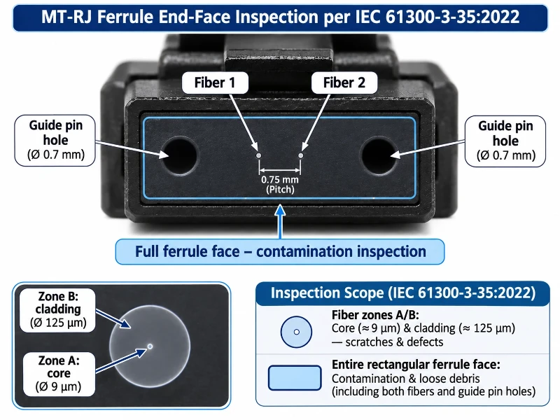
Make the image set traceable to the inspected item. A practical image index should identify:
- The assembly or component identifier and connector end.
- The fiber position shown in each detailed image.
- The image or image set covering the required ferrule contact area.
- The inspection settings, criteria revision and inspection date.
- The relationship between initial images and any post-cleaning images.
If several images are needed, identify them as one coverage set. Use actual inspection images for acceptance evidence; an illustrative image cannot establish the condition of a delivered item.
Clean and Reinspect
If contamination is observed, use the approved cleaning method and inspect again before mating. Cleaning alone does not establish that the interface is ready. Cisco treats inspection, cleaning and reinspection as a connected process.
Distinguish removable contamination from a suspected persistent defect. If cleaning does not resolve the observation, retain the images and refer the item for the specified review. Do not mate a contaminated interface simply because an earlier optical result passed.
A visual nonconformance should follow the approved disposition process. It does not, by itself, establish that permanent disposal is the only possible outcome.
Verify Mating, Mapping and Optical Performance
Check the housing, latch, strain relief and accessible alignment features against the approved drawing. Confirm normal engagement with the specified mating interface. Stop if seating requires unusual force or alignment appears incorrect; do not modify the connector to make it fit.
For a finished assembly, verify each fiber path against the mapping drawing and keep its optical results separately identifiable. Continuity establishes a path; it does not by itself demonstrate compliance with a loss limit.
The finished fiber optic patch cord inspection overview describes continuity, end-face, polarity, appearance and dimensional checks for assemblies. Confirm the applicable scope for the ordered MT-RJ configuration.
Record the Reference Method
Document the test boundary before comparing loss values. Identify the instrument, fiber type, wavelengths, required launch conditions, reference cords, adapters and connections included in the measurement.
Retain separate connection diagrams for setting the reference and measuring the item. Each should identify the source, receiver, cord identifiers, mating interfaces and fiber path. The measurement diagram should also identify the item under test and the boundaries to which the acceptance limit applies.
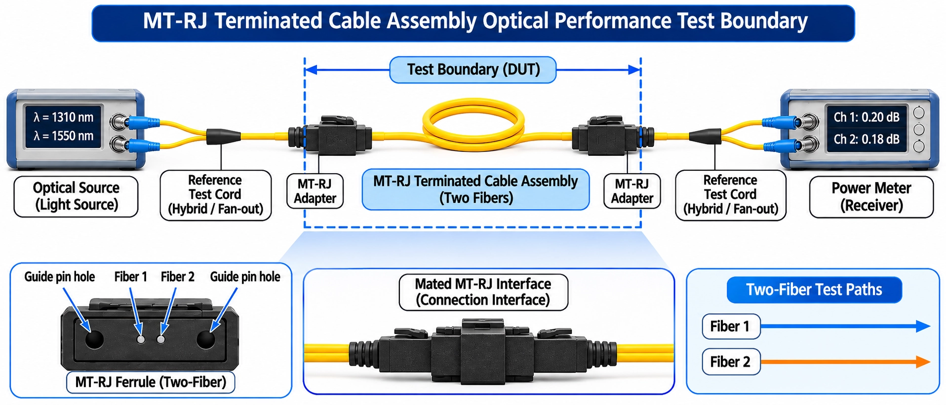
Fluke Networks' 2014 SimpliFiber Pro MT-RJ procedure illustrates why the configuration matters. Its specified setup uses an adapted reference arrangement and a known-good short reference cord to obtain the required pinned connections. It also directs users to test strand A, then reset the reference for strand B. These instructions apply to that instrument and procedure; they are not universal operating steps for every MT-RJ tester.
Use a connection diagram approved for the actual instrument and method. An equipment-specific diagram should not be relabeled as a generic MT-RJ test setup.
Compare Results with the Approved Limits
Use limits agreed for the exact test boundary and conditions. A typical marketing value is not automatically a guaranteed acceptance limit. A complete-link measurement and an individual mated-interface measurement are not interchangeable.
If return loss is required, obtain a result from a method and instrument that measure it. Do not infer return loss from an insertion-loss pass or end-face image. Missing required results leave acceptance incomplete.
For each required optical result, record the item identifier, fiber path, test direction, wavelength, method revision, reference-setup identifier, measured value, unit, applicable limit and disposition. Keep insertion-loss and return-loss results separately identified.
Record Acceptance, Rework and Engineering Review
Use a disposition process that keeps the evidence, decision and authorizing person together. The following routes are suggested quality-management actions and require approval by the responsible quality team.
| Finding | Proposed action | Evidence needed before release |
|---|---|---|
| All required checks meet the approved criteria | Accept within the authorized scope | Complete records and release approval |
| Contamination removable by the approved method | Clean and reinspect; repeat affected tests as required | Post-cleaning evidence and required retest results |
| Incorrect pins, fiber type, mapping or physical damage | Isolate for engineering review or return disposition | Confirmed nonconformance and authorized decision |
| Missing, contradictory or untraceable report | Hold pending clarification | Corrected evidence linked to the delivered item |
Release an item only when all applicable required checks meet the approved criteria, the records are complete and any exceptions have an authorized disposition. Hold release if a required check fails, evidence is missing or an exception remains unresolved. After rework, repeat the affected checks as required and obtain authorized release approval.
Retain original failed results alongside retests. Record what changed, which checks were repeated and who authorized the final disposition.
Where a report is batch-based, state the batch identity, sampled quantity and sampling-plan reference. A sampled result does not establish a measurement for every untested unit. Where individual results are required, verify that each identifier resolves to the supplied assembly.
MT-RJ Inspection and Acceptance Checklist
Use this worksheet after the applicable criteria have been approved. Complete its record header before entering inspection results.
| Record header | Information to enter |
|---|---|
| Item identity | Part number, purchase order, batch or serial number |
| Acceptance basis | Drawing, mapping and specification numbers with revisions |
| Inspection and test setup | Procedure revisions, equipment identifiers and reference-configuration records |
| Record scope | Individual unit or defined batch sample; sampling-plan reference where applicable |
| Review and release | Inspection date, operator, reviewer and authorized release decision |
For every applicable check below, enter the result, record reference and responsible person. Use Pass when the check meets its approved criteria, Fail for a confirmed nonconformance, and Hold when evidence or a decision is pending; these are worksheet conventions, not standardized MT-RJ grades. Mark an item "not applicable" only with a documented reason.
| Object or check | Method | Criteria source | Result | Record reference | Responsible person |
|---|---|---|---|---|---|
| Item identity and test scope | Match label, order and drawing | Purchase order and specification revision | - | - | - |
| Pin configuration and mating interface | Review both mating sides and specified engagement | Interface drawing and equipment documentation | - | - | - |
| Fiber type and both fiber paths | Verify identification and complete the mapping record | Assembly specification and mapping drawing | - | - | - |
| Inspection-tool compatibility | Confirm instrument, tip, accessories and coverage | Equipment instructions and approved procedure | - | - | - |
| Both fiber end faces and contact area | Inspect; clean and reinspect where necessary | Applicable inspection criteria and procedure | - | - | - |
| Housing, latch and strain relief | Inspect and verify specified engagement | Approved mechanical requirements | - | - | - |
| Each fiber's optical performance | Execute the defined reference and measurement method | Approved limits, wavelengths and test boundary | - | - | - |
| Exceptions, retests and release | Review evidence, unresolved findings and authorization | Quality plan and release authority | - | - | - |
Each optical record reference should resolve to the relevant path in the mapping table and its required test conditions. A single "pass" entry should not conceal an untested fiber or missing measurement.
For unassembled components or a passive adapter, replace assembly-only tests with the approved component checks. Do not mark optical performance as measured when no defined optical path was tested.
Confirm the Required Evidence Before Ordering
Send the supplier the item definition, both mating interfaces, fiber type, mapping drawing, required optical tests and report granularity before approving the order. Agree whether the evidence must identify each assembly or a defined batch sample, and establish who will resolve exceptions.
To discuss a proposed configuration with Evolux, use the fiber optic connector specifications and inspection requirements enquiry route and submit those requirements. Confirm the fiber mode and compatibility against the quoted part documentation and equipment-port requirements.
For a custom assembly, use the custom fiber optic assembly test records information to specify the records required with the order. Availability of the particular MT-RJ configuration, test method and report contents should be confirmed in writing before approval.