Technical Specifications – 1×16 Bare Fiber Splitter
| Splitter Type | PLC (Planar Lightwave Circuit) |
| Split Ratio | 1×16 |
| Output Fiber Type | Bare Fiber 250μm Coating (Unconnectorized) |
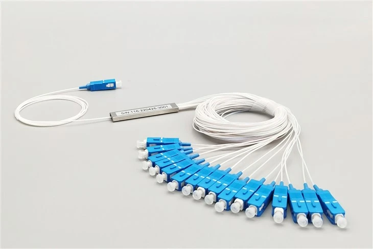
| Package Style | Steel Tube (Mini Tube Metal) |
| Package Dimensions (L×W×H) | 60 × 12 × 4 mm |
| Operating Wavelength | 1260nm ~ 1650nm (Full PON Band) |
| Insertion Loss (Max) | ≤13.5 dB |
| Loss Uniformity (Max) | ≤1.2 dB |
| Polarization Dependent Loss | ≤0.25 dB |
| Return Loss | ≥55 dB |
| Directivity | ≥55 dB |
| Fiber Type | G657A Bend-Insensitive Single Mode |
| Operating Temperature | -40°C to +85°C |
| Storage Temperature | -40°C to +85°C |
| Max Optical Power | 300 mW |
| Humidity Range | 5% ~ 85% RH |
1×16 Splitter Package Comparison: Bare Fiber Steel Tube vs Other Formats
Selecting the right PLC splitter package depends on installation environment, space availability, and whether field fusion splicing or plug-and-play connectivity is preferred. This comparison highlights why the 250μm bare fiber steel tube format excels in space-constrained field deployments.
| Package Type | Dimensions (1×16) | Best For | Connection Method |
|---|---|---|---|
| Bare Fiber Steel Tube | 60 × 12 × 4 mm | Splice closures, tight enclosures | Fusion splicing |
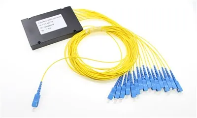
| ABS Module | 120 × 80 × 18 mm | Indoor distribution frames | Pre-connectorized or pigtailed |
| LGX Cassette | Standard LGX footprint | Rack-mount patch panels | Adapter panel connectors |
| 1U/2U Rack Mount | 19" rack width | Central office ODF | Front panel connectors |
The 60×12×4mm steel tube package occupies less than 3% of the volume required by an ABS module splitter, making it the only viable option when multiple 1×16 splitters must fit inside a single splice tray organizer or compact outdoor enclosure.
Why Choose 250μm Bare Fiber Output Over Connectorized Splitters?
The 1×16 bare fiber PLC splitter with 250μm coating eliminates pre-terminated connectors entirely, making it the preferred choice for field technicians who perform fusion splicing at the installation site. Unlike connectorized splitters that require adapter panels and patch cables, this unconnectorized design allows direct fiber-to-fiber fusion, reducing connection points and minimizing potential failure modes in the optical link.
Space Efficiency in Splice Trays and Micro-Closures
With dimensions of just 60×12×4mm, this steel tube bare fiber splitter occupies minimal space inside splice trays, micro-closures, and fiber distribution hubs. Telecom contractors deploying FTTH networks in densely populated urban areas often face severe space constraints inside underground handholes or aerial enclosures. The 250μm bare fiber design allows more splitters per enclosure compared to bulky ABS module or LGX cassette alternatives.
Steel Tube Protection for Harsh Installation Environments
The steel tube package provides mechanical protection during handling and installation without adding unnecessary bulk. Field installers working in outdoor cabinets, pole-mounted closures, or direct-buried enclosures benefit from the rugged metal housing that shields the PLC chip from vibration and physical stress while maintaining the compact footprint essential for space-constrained deployments.
Ideal Deployment Scenarios for 1×16 Bare Fiber Steel Tube Splitters
FTTH Last-Mile Distribution Points
Deployed inside fiber distribution terminals (FDTs) and network access points (NAPs) where a single feeder fiber must serve 16 subscriber drops. The bare fiber output allows direct fusion to individual drop cables without additional connector hardware.
PON Splitter Stages in Central Offices
Used as secondary or tertiary splitter stages in GPON and EPON architectures where space inside ODF frames is limited. The 1×16 split ratio balances subscriber density with acceptable optical loss for metro access networks.
Outdoor Fiber Distribution Cabinets
Installed inside street-level cabinets and pole-mounted enclosures serving residential neighborhoods. The steel tube construction withstands temperature cycling from -40°C to +85°C common in outdoor installations across all climate zones.
Splice Closures for Aerial and Underground Fiber
Integrated into dome closures and inline splice enclosures along fiber routes where technicians perform mid-span splits. The 250μm bare fiber format matches standard splice tray configurations designed for 250μm coated fibers.
FAQ
Q: What fiber length options are available for bare fiber 1×16 splitters?
A: Standard configurations include 1.0m and 1.5m fiber lengths on both input and output sides. Custom lengths from 0.5m to 3.0m can be specified for projects requiring longer reach inside large enclosures or direct routing to patch panels.
Q: Can I add connectors to the bare fiber outputs after installation?
A: Yes. Field-installable connectors or factory-polished pigtails can be fusion spliced to the 250μm bare fiber outputs. However, this adds connection points and potential loss. If pre-connectorized outputs are needed, consider ordering an ABS module or LGX cassette version instead.
Q: What splicing equipment is required to install 250μm bare fiber splitters?
A: Standard single-fiber fusion splicers with 250μm fiber holders are sufficient. No special tooling is required beyond typical FTTH installation equipment including fiber cleavers, strippers, and protective splice sleeves.
Q: How does the steel tube package protect the splitter chip?
A: The stainless steel tube encases the silica PLC chip and bonded fiber array, providing crush resistance, vibration dampening, and moisture barrier protection. This is more robust than bare plastic encapsulation while maintaining smaller dimensions than ABS module housings.
Q: Is this splitter suitable for outdoor direct burial applications?
A: The splitter itself is rated for -40°C to +85°C operation, but bare fiber outputs require protection inside a sealed enclosure. For direct burial, install the splitter inside a gel-sealed splice closure designed for underground environments.
Q: What is the difference between 1×16 and 2×16 splitter configurations?
A: A 1×16 splitter has one input fiber serving 16 outputs. A 2×16 configuration provides two independent inputs, each serving 8 outputs, useful for dual-OLT redundancy or serving two separate PON trees from the same splitter location.
Q: Can this splitter handle bidirectional PON signals at 1310nm and 1490nm simultaneously?
A: Yes. The 1260-1650nm operating wavelength range covers all standard PON bands including GPON downstream (1490nm), upstream (1310nm), and video overlay (1550nm) without wavelength-dependent loss variation.
Q: What quality testing is performed before shipment?
A: Each splitter undergoes 100% optical testing including insertion loss measurement at 1310nm and 1550nm, return loss verification, and uniformity checks across all output ports. Test reports are available upon request.
Need Custom Fiber Lengths or High-Volume Pricing?
Contact our engineering team for project-specific configurations of 1×16 bare fiber PLC splitters.
Hot Tags: 1x16 bare fiber plc splitter, 250um plc splitter steel tube, compact ftth splitter 1x16, bare fiber optical splitter for pon, fiber optic plc splitter for lan, fiber optic plc splitter sample, fiber optic plc splitter recommendation, odm fiber optic plc splitter, fiber optic plc splitter integration, fiber optic plc splitter industry standard