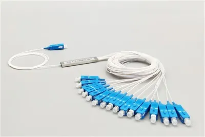
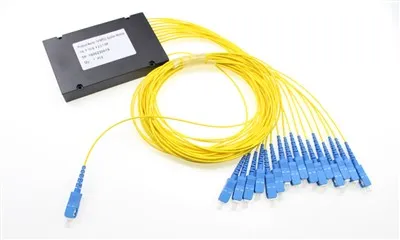
the usage steps of fiber optic splitter
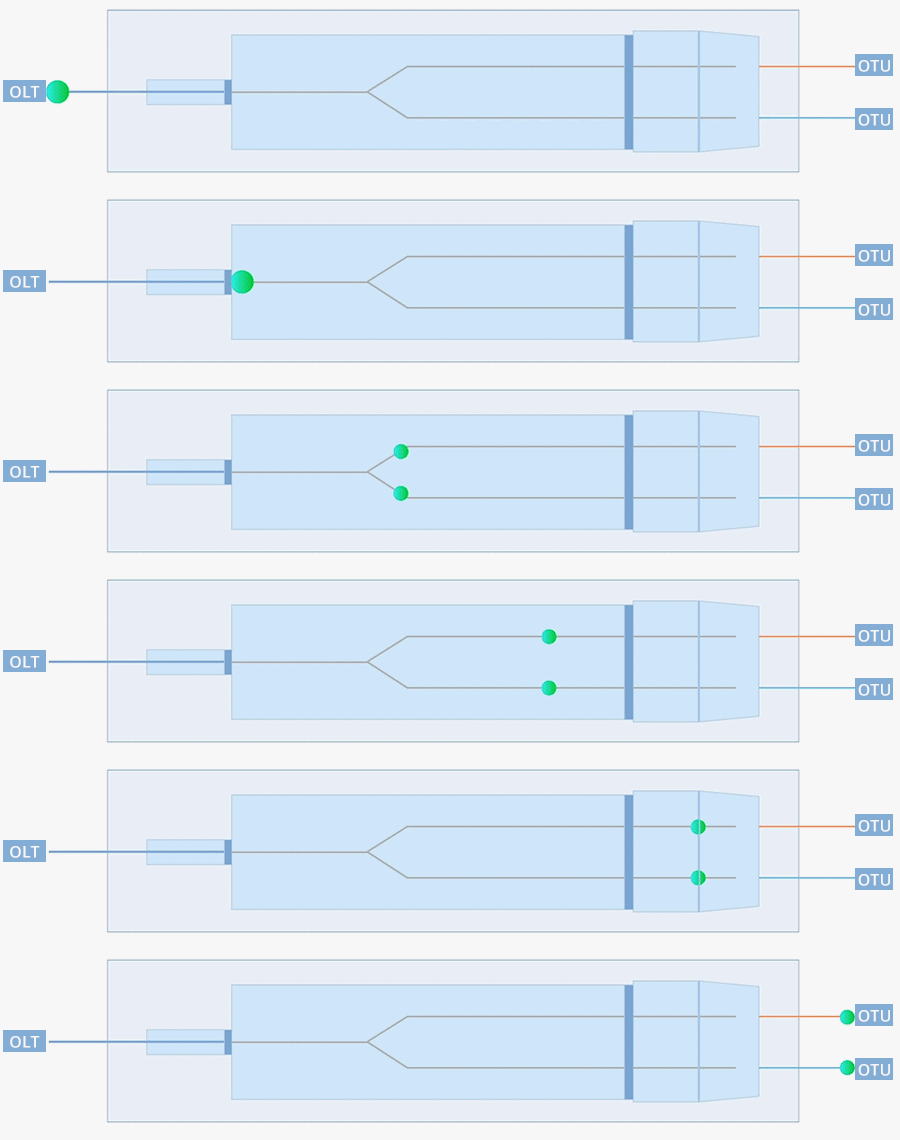
Optical splitter is an essential component in Passive Optical Network (PON), used to distribute a single input fiber signal to multiple output fibers or merge multiple input fiber signals into one output fiber. This article will analyze the detailed usage methods and steps of fiber optic splitters.
1, Preparation work
1. Tools and materials
Fiber optic cutting knife: used for precise cutting of optical fibers.
Fiber optic cable stripping pliers: used to remove the coating layer on the outer layer of optical fibers.
Fiber optic cleaning tools: such as alcohol swabs, fiber optic cleaning pens, etc., used to clean fiber optic connectors.
Fiber optic jumper: used to connect fiber optic splitters and equipment.
Optical power meter: used to measure the intensity of optical signals.
OTDR (Optical Time Domain Reflectometer): used to detect loss points and breakpoints in fiber optic links.
2. Check the equipment
Check the splitter: Ensure that the fiber optic splitter is not physically damaged, and that the connectors are clean and intact.
Check the fiber optic cable: Ensure that the fiber optic cable is not significantly damaged or bent.
2, Installation steps
1. Clean the connector
Clean the input end: Use fiber optic cleaning tools to thoroughly clean the input end connector of the fiber optic splitter.
Clean the output end: Also clean the connectors of each output port to ensure that there is no dust or dirt.
2. Prepare fiber optic cables
Cutting optical fibers: Use a fiber optic cutting knife to cut the optical fibers into flat end faces, ensuring a smooth cut.
Peel off coating layer: Use fiber optic cable stripping pliers to peel off the coating layer of the optical fiber, exposing the bare fiber part.
Clean the bare fiber: Use an alcohol swab or fiber optic cleaning pen to clean the bare fiber part, ensuring that there is no dust or grease.
3. Connecting optical fibers
Insert input end: Insert the processed fiber optic cable into the input connector of the fiber optic splitter and ensure a secure connection.
Insert output end: Insert multiple processed optical fibers into each output port connector of the fiber optic splitter, and ensure that each connection is secure.
4. Fixed connection
Thread locking: If using SC or LC type connectors, it is usually necessary to lock them by rotating the connector housing.
Buckle locking: If MPO or MTP type connectors are used, there is usually a buckle device that automatically locks.
3,Testing and Validation
1. Optical power testing
Measure input end: Use an optical power meter to measure the optical power at the input end and record the initial value.
Measure the output end: sequentially measure the optical power of each output port and record the optical power value of each port.
Calculate loss: Calculate the insertion loss of each output port based on the optical power values at the input and output terminals. Insertion loss=input optical power - output optical power.
2. OTDR testing
Link detection: Use OTDR to detect the entire fiber optic link, including all paths from the central office to the user end.
Problem finding: By using the waveform diagram of OTDR, specific loss points or breakpoints can be located to determine whether there is a fault.
3. Check for uniformity
Compare ports: Compare the optical power values of each output port to ensure that the differences between them are within an acceptable range. Usually, uniformity refers to the difference between the maximum insertion loss and the minimum insertion loss.
4, Installation precautions
1. Avoid excessive bending
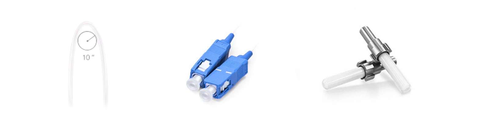
Bending radius: Optical fibers should avoid excessive bending to prevent signal loss. Generally speaking, the bending radius should not be less than 10 times the diameter of the optical fiber.
2. Dustproof and Waterproof
Good sealing: Ensure that the connection is well sealed to prevent dust and moisture from entering, especially in outdoor environments.
3. Identification management
Clear identification: Clearly label each optical fiber for easy management and maintenance. Labels or markers can be used to make marks on the fiber optic cable.
5, Maintenance and troubleshooting
1. Regular inspection
Cleaning: Regularly clean the surfaces of connectors and splitters to maintain cleanliness.
Check connection: Regularly check if the fiber optic connection is secure, loose, or damaged.
2. Troubleshooting
Optical power test: If the optical power of an output port is found to be abnormally low, it may be due to poor connection or problems with the splitter itself.
Replace components: If the splitter or connector is found to be damaged, it should be replaced in a timely manner.
Reconnect: If the connection is loose, unplug and ensure the connection is secure.
The use of fiber optic splitters mainly includes several key steps, including preparation work, installation steps, testing and verification, as well as maintenance and troubleshooting. Proper installation and maintenance can ensure the stability and reliability of fiber optic networks. By following the above steps and precautions, you can effectively use fiber optic splitters to meet the needs of various application scenarios.
Features
application

FTTH/FTTX - Residential Broadband
- GPON/EPON distribution networks
- Residential fiber-to-the-home rollouts
- Multi-dwelling unit (MDU) deployments
- Last-mile fiber distribution

Enterprise & Data Center Networks
- LAN backbone signal distribution
- Server room optical connectivity
- Campus network infrastructure
- Point-to-multipoint fiber links

CATV & Broadcast Systems
- Cable television signal splitting
- Video distribution networks
- RF over fiber applications
- Broadcast headend systems

Testing & Monitoring
- Optical signal monitoring tap points
- Network performance testing
- Fiber optic sensor systems
- Laboratory measurement setups
FAQ
Q: Why choose a 1×2 PLC splitter over an FBT splitter?
A: Great question! For a 1×2 split, you could technically go with either PLC or FBT – both work. But here's the thing: if you're planning to scale up later or need rock-solid wavelength consistency across 1260-1650nm, PLC is the way to go. FBT splitters can have slight wavelength-dependent loss variations, while our PLC splitters deliver uniform performance whether you're running 1310nm, 1490nm, or 1550nm signals. Plus, PLC handles temperature swings (-40°C to +85°C) like a champ – we've had customers deploy these in outdoor cabinets from Scandinavia to the Middle East without issues.
Q: What's the difference between SC/UPC and SC/APC connectors?
A: This comes up a lot! SC/UPC (Ultra Physical Contact) has a flat polished end face and typically provides ≥50dB return loss – it's perfect for most data communication and LAN applications. SC/APC (Angled Physical Contact) has an 8-degree angled polish that gives you better return loss (≥55dB), which matters more for analog signals like CATV or when you're running long-haul links where back-reflections can cause issues. For standard GPON/EPON setups, either works fine, but if your network uses a mix, make sure you're matching connector types – UPC to UPC, APC to APC.
Q: How much signal loss should I expect from a 1×2 PLC splitter?
A: For a 1×2 split, you're looking at roughly ≤4.1dB insertion loss per output port – that's the theoretical 3dB split loss plus a small amount of excess loss from the chip itself. Our splitters typically come in at the lower end of that range. Keep in mind this is significantly better than daisy-chaining multiple couplers. The uniformity between the two output ports is within ±0.6dB, so your downstream equipment sees balanced signals. For your link budget calculations, I'd recommend using 4dB as a safe planning number.
Q: Can I use this splitter bidirectionally?
A: Absolutely – PLC splitters are fully passive and work in both directions. You can use it as a 1×2 splitter (one input, two outputs) or flip it around as a 2×1 combiner (two inputs, one output). This makes them perfect for PON applications where you've got downstream broadcast signals and upstream data from ONTs sharing the same fiber. Just remember that in combiner mode, you'll still see that ~3.5dB loss from each input to the output – physics doesn't change!
Q: What's the difference between mini tube and ABS box packaging?
A: Think of it this way: the mini tube (what this product uses) is compact and great for space-constrained installations like splice trays, distribution boxes, or rack-mount panels. It's got a small footprint and the fiber pigtails come out neatly from one end. ABS box packaging, on the other hand, wraps everything in a sturdy plastic enclosure – it's bulkier but offers better protection and easier handling for field technicians. For most indoor FTTH, enterprise closets, and ODF installations, the mini tube is the go-to choice. We typically recommend ABS boxes for outdoor cabinets or when installers need quick plug-and-play deployment.
Q: How do I know if my splitter is working correctly after installation?
A: Simple field test: use an optical power meter. Inject a known power level (say, 0dBm at 1310nm or 1550nm) into the input port, then measure each output. You should see roughly equal power on both outputs, around -3.5 to -4dB from your input. If one port shows significantly higher loss or no signal, check your splice points first – 9 times out of 10, it's a fusion splice issue, not the splitter. We 100% test every unit before shipping with insertion loss, uniformity, and return loss measurements, so if you're seeing problems right out of the box, reach out to us with your test results and we'll sort it out.
Q: Is this splitter compatible with both GPON and EPON systems?
A: 100% yes! Our PLC splitters are wavelength-independent across the entire 1260-1650nm range, which covers all the wavelengths used in both GPON (1310nm upstream, 1490nm downstream) and EPON (1310nm/1490nm) systems. They also work great with XGS-PON, 10G-EPON, and even WDM-PON deployments. The beauty of PLC technology is that you don't need to worry about wavelength-specific components – one splitter handles everything. We've seen these deployed in mixed networks where carriers are running multiple PON technologies on the same ODN infrastructure.
Q: What fiber cable diameter options are available?
A: We offer several options to match your installation needs. The standard configuration comes with 900μm tight-buffered fiber, which is the most popular for indoor distribution boxes and ODF panels. We also offer 2.0mm and 3.0mm cable versions if you need more rugged protection or prefer the easier handling of thicker cables. For bare fiber applications where you're fusion splicing directly, we can provide 250μm versions as well. Just let us know your requirements when ordering – we're flexible on fiber length too, typically from 0.5m up to 2m or custom lengths.
Hot Tags: 1×2 plc fiber splitter mini tube sc upc, China 1×2 plc fiber splitter mini tube sc upc manufacturers, suppliers, factory, fiber optic plc splitter standard compliance, promotion of fiber optic plc splitter, fiber optic plc splitter for fttx, packaging of fiber optic plc splitter, fiber optic plc splitter sample, purchase fiber optic plc splitter